


36
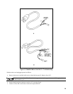
d. Place the front panel power-on switch in the off position. Remove the ac input cover from the rear panel and connect the
"L" and "N" screws on the barrier block to the output of the external DC supply. If a line cord is already connected to
these terminals, construct an adapter as shown in Figure 3-2 (a), which allows you to connect the cord to the DC supply.
In either case ignore polarity as the unit's rectifying diodes steer the dc power to the correct nodes.
e.
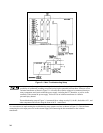
Complete the setup of Figure 3-1 by attaching an ac mains cord to test points J8 (L, black wire) and J7 (N, white wire)
and connect the green ground wire to the unit's case ground terminal or a suitably grounded cabinet screw. See Figure
3-2 (b). Plus the mains cord into an isolation transformer.
Troubleshooting No-Output Failures
Note The main troubleshooting setup is not used for the No Output Failures and Front Panel troubleshooting
tests.
No-output failures often include failure of the A4Q1 through A4Q4 PFETs and their fuses, A4F1 and A4F2. When either
the off-pulses or the power-limit comparator fails, the PFETs can fail from excessive power dissipation. The strategy for
localizing no-output failures is to check the voltages and waveforms at the control board test connector to predict if that
circuit failure would cause the PFETs to fail. This makes it possible to develop your troubleshooting approach without an
extensive equipment setup. Proceed as follows:
a.
With the mains cord unplugged remove the A4 FET Driver board as described on page 30. Plug in the mains cord and
switch on power.
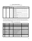
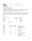
b.
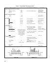
Using Table 3-1 check the bias voltages, the PWM-OFF, PWM-ON and Ip MONITOR Control signals and other
signals of interest at the A2 control board test fingers, A2J7.
c.
Check for the presence of program voltages, VP and IP, at the rear panel.
d.
Check for presence of the 320Vdc rail voltage between the rear facing end of AlR3 and the rear facing end of AlR1. If
there is no rail voltage, check diode Assembly A1U1.
A1R1, A1R3, and AlU1 connect to the ac mains voltage. Use a voltmeter with both input terminals floating
to measure the rail voltage.
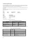
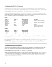
e. Select the functional circuit for troubleshooting based on your measurements and Table 3-2, which provides direction
based on the status of the PWM OFF and PWM ON signals .
Front Panel Troubleshooting
Troubleshoot the A3 front panel board by first doing the following setup:
a.
Remove the top plastic insert from the front frame by prying up with a flat-blade screwdriver.
b.
Remove the 4 front panel assembly mounting screws (Phillips 6-32), two on top and two on the bottom.
c.
Detach the A3 board from the front panel assembly by removing the 6 mounting screws (Pozidriv, M4x7).
d.
Place the A3 board vertically against the supply with a piece of insulating material between. The test connector can
then be attached to the A3 board. The rest of the front panel assembly can stand vertically so that the pots and the
switches can be accessed while troubleshooting.
e.
Plug in the mains cord and switch on power.
The ac mains voltage connects directly to the LINE switch and to components and traces at the front of the
A1 main board. Be extremely careful to avoid touching the ac mains voltage.
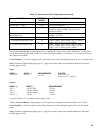
Start troubleshooting by performing the tests given in Table 3-3. This table provides the measurements for the test points on
the test connector as well as the source components for that measurement. Table 3-4 gives front panel symptoms as well as
the circuits or components that may cause the supply to exhibit those symptoms. Both Tables 3-3 and 3-4 should be used to
check out and troubleshoot the front panel.