


38
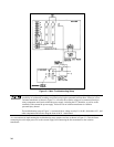
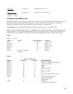
Troubleshooting Bias Supplies
+5V on A2 Control Board. The PWM A2U22 includes a clock generator (40KHz set by A2R170, A2C79, and A2Q10),
and a current limit (2Adc set by 0.15Vdc across A2R172). It turns off each output pulse using the difference between the
voltage at voltage divider A2R161-A2R163 and the 2.5Vdc set by voltage regulator A2U21.
Circuit Included. + 5Vdc bias supply circuitry from connector pin A1J5-1,3 (1,3 both pins) through jumper A2W3 on A2
control board.
Setup. The Main Troubleshooting Setup, page 33. Apply the ac mains voltage to the isolation transformer, and set the
external supply to 0Vdc.
Input:
NODE + NODE - MEASUREMENT SOURCE
A2J7-22 A2J4-4.
≈ 20Vdc
A1CR2,AlCR5
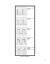
Outputs
NODE MEASUREMENT
A2U22-6
≈ 2 to 4Vdc sawtooth, 40KHz
A2U22-12,13
≈ 19Vpk, 15µs pulses, 40KHz
A2Q9 (emit)
≈ 20Vpk, 5µs pulses, 40KHz
A2U21 -2 2.5Vdc
A2R161, A2R163 2.5Vdc
To check if load on + 5V is shorted, remove jumper A2W3
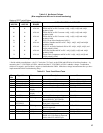
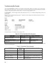
Table 3-4. A3 Front Panel Board Failure Symptoms
SYMPTOMS DEFECTIVE CIRCUIT CHECK COMPONENTS
Error when pressing DISPLAY SETTINGS Limits display. A3U5, A3U8
Error in VOLTS or AMPS Input ranging or DVMS. A3U8,A3U6,A3U4,A3U1,A3U2,
A3U7
* One or more display digits out Display LEDs. A3DS1 through A3DS8
Unable to adjust VOLTAGE or CURRENT
or always max
Potentiometers. A3R99, A3R100
VOLTS decimal point error Decimal drivers. A3U3
* Note that the Volts and Amps tests (Table 3-3 pins 5 and 6) verify that all the current and voltage display segments light
except for the decimal points.
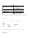
Table 3 5. Performance Failure Symptoms
SYMPTOMS DEFECTIVE
BOARD
CHECK FUNCTIONAL CIRCUITS
Unexplained OVP shutdowns A2 OVP Circuit, CV Circuit
No current limit A2 CC Circuit
Max current < 17Adc A2 CC Clamp, CC Circuit
Max power < specified A2, A1 Power Limit, 20KHz clock, transformer A1T2
Max voltage < 200Vdc A2, A1 CV Circuit, diodes A1U1, mains voltage select
jumper A1W1
Cycles on & off randomly A2, A1 AC-Surge-&-Dropout Detector, Mains Voltage
Select switch A1S2