96
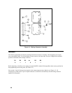
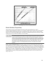
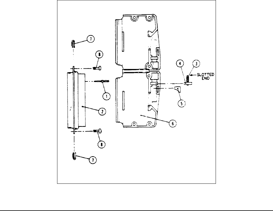
Figure A-1. Mating Connector Assembly
Operation
The following paragraphs provide the operating instructions necessary to interface a 002-equipped power supply
into an automated system. A brief description of some circuits is also provided. The unit is shipped for front panel
operation with mode switch settings as follows:
B1 B2 B3
B4
B5 B6
011011
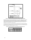
Before beginning, switch the power supply's rear panel MODE switches B1 through B6 to their correct positions for
the programming source being used, (see Table A-2).
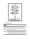
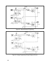
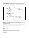
Next switch A1 and A2 also on the rear panel, to the correct program source function, see Figure A-2. All
connections are made at the 37-pin rear panel connector J3, and can be wired directly into the mating connector
supplied for this purpose.


