107
Troubleshooting
Before attempting to troubleshoot the 002 Option Board, ensure that the fault is with the option itself and not with
the main power supply. This can be accomplished by removing the top cover, inside cover and disconnecting the
two ribbon cables from the A2 Control board and checking the operation of the main supply. Otherwise troubleshoot
the option board as described in the following paragraphs.
Removal of the Option Board. To facilitate troubleshooting the 002 Option the board can be removed from the
power supply and electrically connected via the ribbon cables from Service Kit's 06033-60005 or 5060-2665. To
remove the circuit board proceed as follows:
a.
Turn off power supply and disconnect line cord.
b.
Disconnect option I/O cable from J3 on rear panel and remove the two screws that secure option board to rear
panel.
c.
Disconnect the ribbon cables from the A2 Control board.
d.
Remove option board by lifting the board by the front edge and sliding the board toward the front of the power
supply.
e.
Reconnect the option board to the A2 Control board using the extended ribbon cables from the Service Kit, and
pace the option board on an insulated surface next to the power supply.
f. Be careful that the option board lies securely on insulating material and does not touch any part of the main
power supply.
Isolating Faulty Circuit. If it is apparent which function is not operating properly, proceed to the appropriate
paragraph. If the problem involves more than one function, check the bias voltages from connectors J1 and J2 and
the
± 11.8V on the option board.
Troubleshooting Resistance and Voltage Programming
a. Confirm that the problem is on the option board by disconnecting the ribbon cables from the A2 Control Board
and attempting to program the supply via the rear panel terminal strip.
b.
Check ± 15V and ± 11.8V supplies.
c. Check for a problem in the programming protection circuit. This circuit should draw about 2µA from the
programming lines.
d.
Check that W3 and W4 are installed and S1 is in proper position .
Troubleshooting Current Programming
a. Check ± 15V and ± 11.8V supplies.
b.
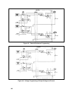
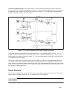
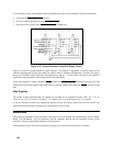
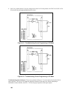
Proceed to test set-up shown in Figure A-11 and/or A-12.
c.
Put S1 in V, R position and see if varying the 0-20V voltage source produces a 0-5 volt DC level across R44 or
R39. If not, check op-amps and associated circuitry.


