


208
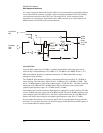
Module Description
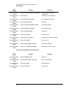
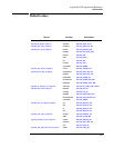
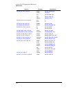
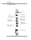
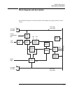
Front Panel Description
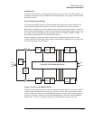
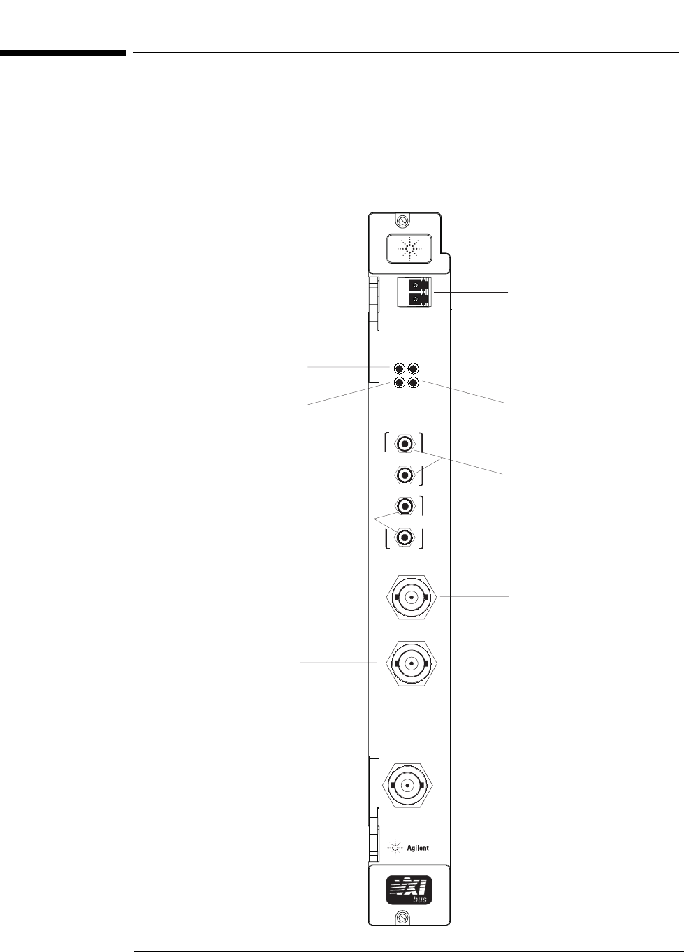
Front Panel Description
Intermodule ( ECL )
Clock
Sync
Ext Clock/Ref
Ext Trigger
Analog In
5Vrms Max
Access
Overload
LED lights when the module is accessed
via the VXI backplane.
Sync extenders are used to extend the
sync line from one mainframe
or module to another. It is an SMB connector
for ECL levels and must be terminated in
50 ohms at each end of the chain.
BNC input for ECL or TTL signals that can trigger
data acquisition. For ECL, the input is ac coupled,
1 k ohm, edge sensitive. For TTL, the input is
dc coupled, 1 k ohm, TTL levels.
This is the main input to the ADC. It is a
single-ended input terminated into 50 ohms.
Clock Extenders are used to connect the
system reference from one mainframe or
module to another. It is an SMB connector
for ECL levels and must be terminated in
50 ohms at each end of the chain.
BNC input for TTL, ECL, or sine
wavesignals that can be used as the
ADC sample clock. This input can also
be used for the system frequency reference.
This input is ac coupled, and has1kohm
impedance.
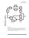
XMT RCV
I/O
Data
XMT
RCV
LED lights when the transmitter is enabled.
LED blinks when data generated by this module
is being transmitted. (”D” module only)
LED lights when an optical signal is detected.
LED blinks when data is being received.
(”D” module only)
Fiber optic serial FPDP data link.
Dual LCconnector.
(”D” module only)
exceeded, producing an overload in the ADC
LED lights whenever the input range is