


217
Module Description
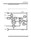
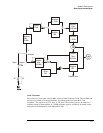
Block diagram and description
Trigger Detection
The trigger event used to start a measurement can be generated in five different ways:
•Software
• External
• ADC threshold
• Log-magnitude
• Immediate
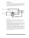
External and ADC threshold triggering modes support slope selection. In ADC or log-magnitude
mode, the trigger threshold has hysteresis (20 ADC sample counts for the ADC trigger, and 1.5
dB for the magnitude trigger) to prevent noise-generated triggers of the wrong slope. Log
magnitude triggering is based on the magnitude of the complex signal after zooming and filtering
and only supports positive slope trigger detection.
The external trigger mode is selectable between ECL and TTL. The trigger signal must be
connected to the Ext Trigger BNC connector on the front panel. In ECL trigger mode, this input is
ac coupled with an impedance of 1 k ohm so any signal with a sharp rising or falling transition
greater than 100 mV (i.e., TTL or ECL) can be used as an external trigger source. Minimum pulse
width is 300 ns. Since the ECL trigger input is an ac-coupled comparator with hysteresis, its
initial state is unknown. Before using it, a trigger pulse should be applied to the Ext Trigger
connector to initialize it to a known state. In TTL trigger mode, the external trigger input is dc
coupled with an impedance of 1 k ohm and uses normal TTL level thresholds (0.8 V and 2.0 V).
Note External TTL trigger is not supported on E1439A modules with serial numbers lower than
US41140000.
Any E1439 module can trigger other E1439 modules using a shared sync line on the VXI
backplane. This Sync line can be extended to other mainframes by connecting a "Sync" SMB
connector in one mainframe to a "Sync" SMB connector on an E1439 in the second mainframe.
All modules in a synchronous system are triggered on the same ADC sample.
The E1439 hardware samples the trigger source once every sample clock, so the trigger condition
must be present for at least one sample clock in order to be recognized.
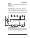
Control Registers
The E1439 module is controlled by firmware using registers mapped into the 16-bit VXI address
space.