


Chapter 1: Overview
20
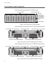
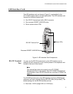
Front and Rear Panel Components
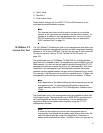
Figure 2 shows the front panel of the AT-CV5000 chassis.
Figure 2. Front Panel of the AT-CV5000 Chassis
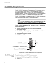
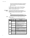
Figure 3 illustrates the rear panel of the AT-CV5000 AC powered chassis.
Figure 3. Rear Panel of the AT-CV5000 Chassis (AC Version)
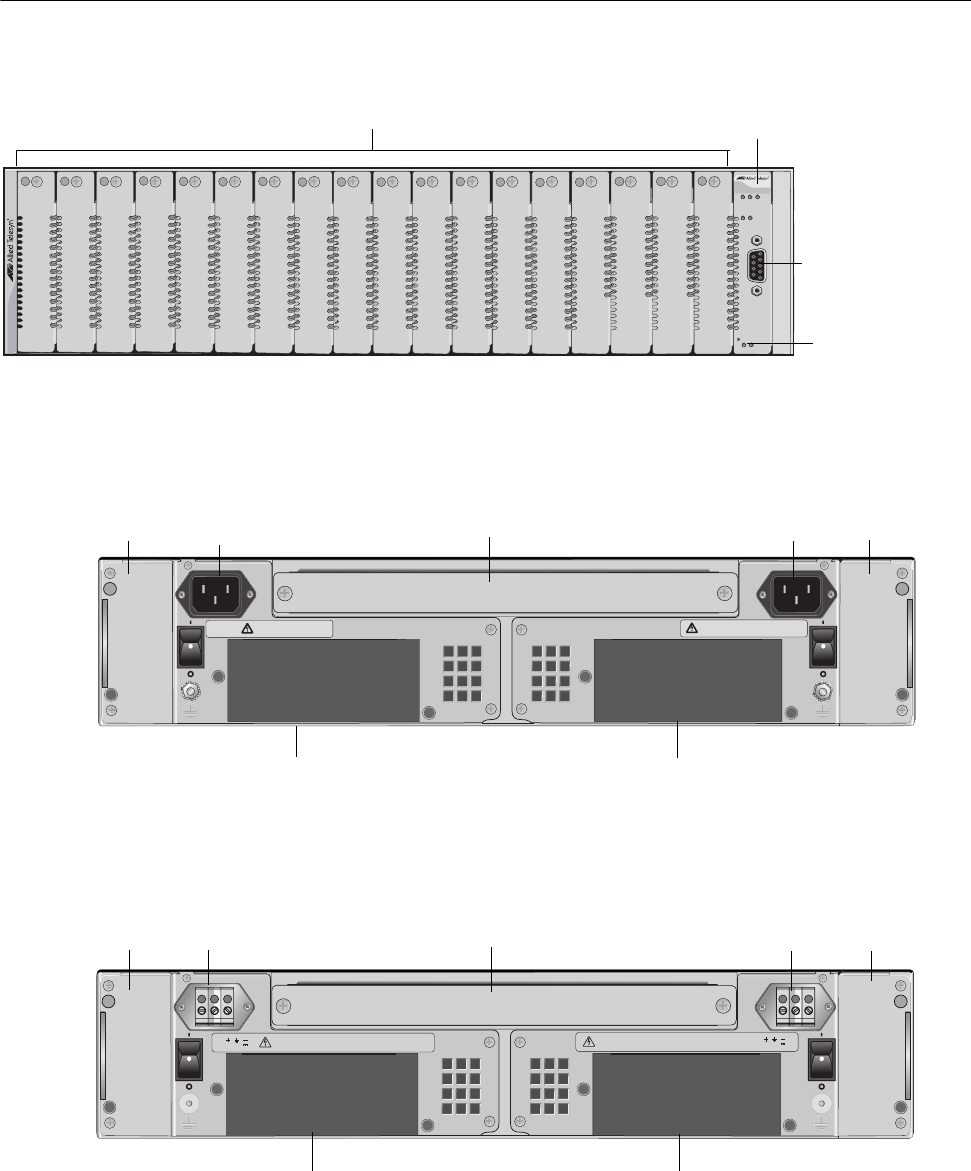
Figure 4 illustrates the rear panel of an AT-CV5000 DC powered chassis.
Figure 4. Rear Panel of the AT-CV5000 Chassis (DC Version)
Line Card Slots
LED Interface Card
FAN 1
PS1
RDY
AT-CV5000
AT-CV5LED
R
D
Y
F
L
T
M
A
S
T
E
R
R
ESE
T
L
IN
E/E
X
P
PS-A PS-B
F
A
N
-A FA
N
-B
REAR EXP. CONSOLE
1
2
3
4
5
6
7
8
9
10
11
12
13
14
15
16
17
18
269
Reset Button
RS-232
Terminal Port
(to manage any
module in the
rear expansion
slot)
AB
AT-CVFAN
A
AT-CVFAN
B
214
REAR EXP. SLOT
100-240VAC~
WARNING
This unit might have more than one power input. To
reduce the risk of electric shock, disconnect all power
inputs before servicing unit.
100-240VAC~
WARNING
This unit might have more than one power input. To
reduce the risk of electric shock, disconnect all power
inputs before servicing unit.
AT-PWR14 Power Supply Module Optional Redundant Power Supply Slot
Fan Tray Slot
Fan Tray Slot
AC Power Socket Rear Expansion Slot AC Power Socket
DC Terminal Block
AB
AT-CVFAN
A
AT-CVFAN
B
40-60VDC
WARNING
This unit might have more than one power input.To
reduce the risk of electric shock, disconnect all power
inputs before servicing unit.
FOR CENTRALIZED DC POWER
CONNECTION, INSTALL ONLY IN
A RESTRICTED AREA.
40-60VDC
WARNING
This unit might have more than one power input.To
reduce the risk of electric shock, disconnect all power
inputs before servicing unit.
FOR CENTRALIZED DC POWER
CONNECTION, INSTALL ONLY IN
A RESTRICTED AREA.
221
AT-PWR15 Power Supply Module
Optional Redundant Power Supply Slot
Fan Tray Slot DC Terminal Block
Fan Tray Slot
Rear Expansion Slot