


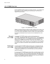
AT-CV5000 Media Converter Chassis Installation Guide
21
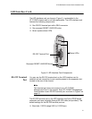
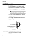
LED Interface Card
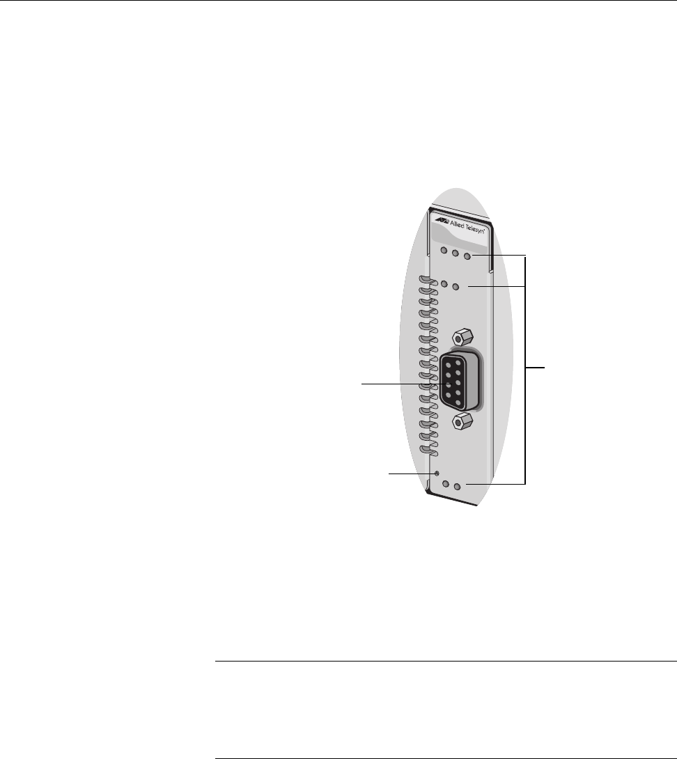
The LED interface card, as shown in Figure 5, is preinstalled in the
AT-CV5000 chassis and is not field-replaceable. The LED interface card
features the following components:
One RS-232 terminal port with a DB-9 connector
One recessed RESET LINE/EXP button
Seven system status LEDs
Figure 5. LED Interface Card Components
RS-232 Terminal
Port
You can use the RS-232 terminal port on the LED interface card to
establish a local connection to any module present in the expansion slot
located in the rear of the chassis.
Note
This terminal port does not connect to any AT-CV5M01
Management Card in the chassis. Each AT-CV5M01 Management
Card contains its own RS-232 terminal port, as shown in Figure 6 on
page 24.
The RS-232 terminal port on the LED interface card has a DB-9 female
connector and uses a straight-through RS-232 cable (not provided). The
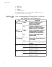
default settings for the RS-232 terminal port are:
Baud rate: 115200 (range 2400 to 115200 bps)
251
FAN1
PS1
RDY
AT-CV5LED
RDY MSTR FLT
RESET LINE/EXP
PS-A PS-B
FAN-A F
AN-B
. SLO
REAR SLOT CONSOLE
Status LEDs
Recessed RESET LINE/EXP Button
RS-232 Terminal Port