


AT-CV5000 Media Converter Chassis Installation Guide
83
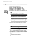
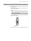
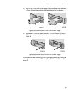
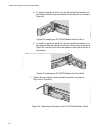
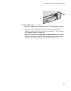
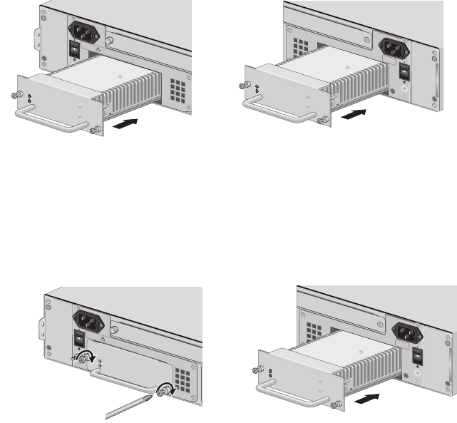
5. Slide the AT-PWR14 power supply into the selected slot, as shown in
Figure 56, until the module is flush with the front of the chassis.
Figure 56. Inserting the AT-PWR14 AC Power Supply
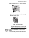
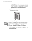
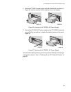
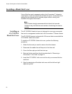
6. Secure the AT-PWR14 AC power supply to the AT-CV5000 chassis by
using a Phillips screwdriver to tighten the captive screws, as shown in
Figure 57.
Figure 57. Securing the AT-PWR14 AC Power Supply
For information about powering on an AC-powered chassis and starting a
management session, refer to “Powering On an AC Powered Chassis” on
page 60.
209
A
1
0
0
-
2
4
0
V
A
C
~
POWER
FAULT
AT-PW
R14
A
W
A
R
N
I
N
G
T
h
i
s
u
n
i
t
m
ig
h
t
h
a
v
e
m
o
r
e
t
h
a
n
o
n
e
p
o
w
e
r
in
p
u
t
.
T
o
r
e
d
u
c
e
t
h
e
r
is
k
o
f
e
l
e
c
t
r
i
c
s
h
o
c
k
,
d
i
s
c
o
n
n
e
c
t
a
l
l
p
o
w
e
r
B
1
0
0
-2
4
0
VA
C
~
AT-CV5FAN
B
1129
P
OWE
R
F
A
U
LT
AT
-PW
R1
4
PWR A
PWR B
A
1
0
0
-
2
4
0
VAC
~
P
O
WER
F
A
U
LT
AT-PWR14
A
AT-CVFAN
1
0
0
-
2
4
0
VAC
~
WA
R
N
I
N
G
Th
is unit might h
ave more than one p
o
wer input
.
T
o reduce the
risk of electric shoc
k,
disconnect all power inputs before
ser
vicing unit.
212
PWR A
PWR B
B
1
0
0
-2
4
0
VA
C
~
AT-CV5FAN
B
1129
P
OWE
R
F
A
ULT
AT
-PW
R1
4