


AT-CV5000 Media Converter Chassis Installation Guide
87
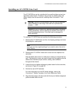
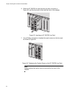
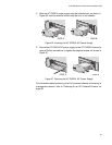
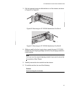
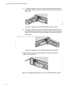
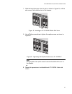
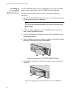
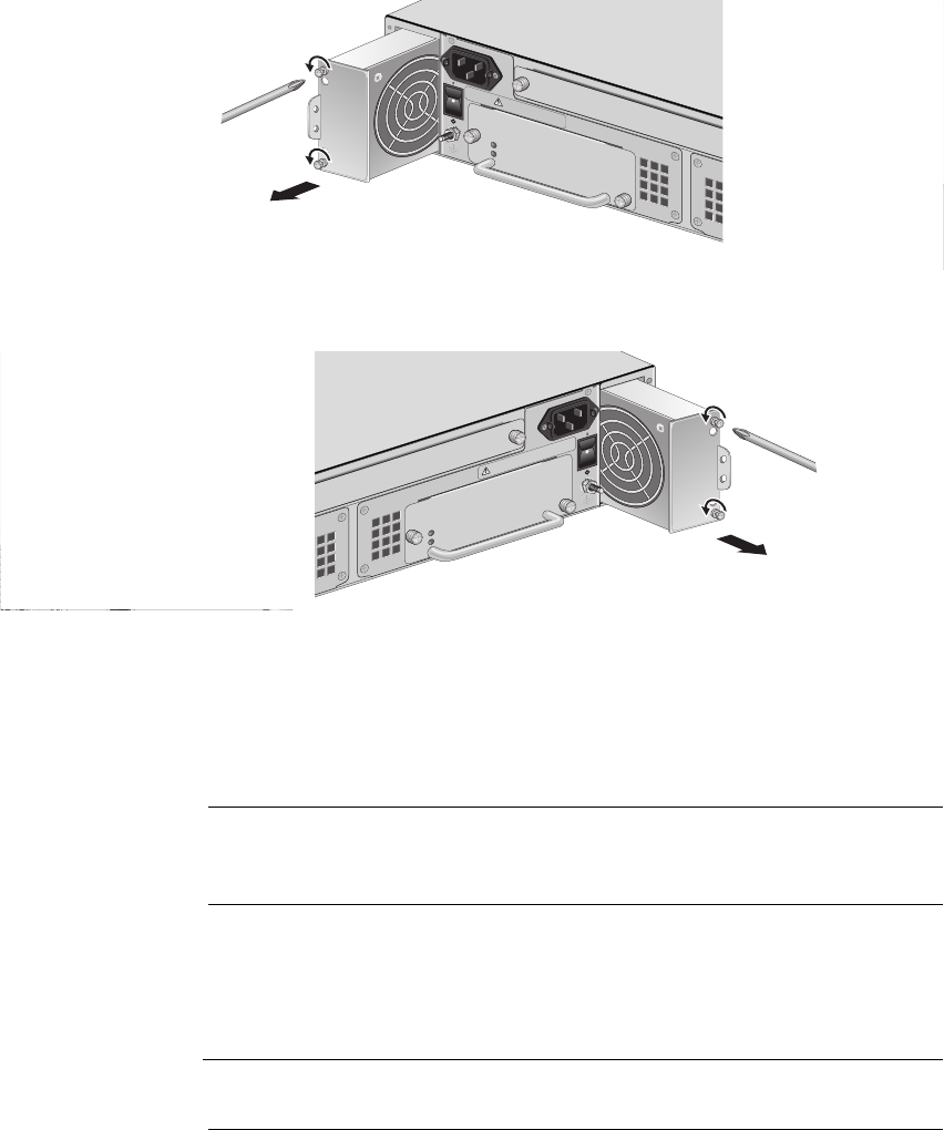
3. Pull the loosened screws to slide the fan out of the chassis, as shown
in Figure 60 or Figure 61.
Figure 60. Removing an AT-CVFAN Module from Fan Slot A
Figure 61. Removing an AT-CVFAN Module from Fan Slot B
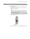
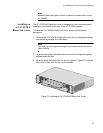
4. While you wait for the fan to spin down, unpack the new AT-CVFAN
module from the shipping package and store the packaging material in
a safe location.
Note
You must use the original shipping material if you need to return the
fan module to Allied Telesis.
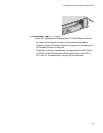
5. Carefully remove the fan module from the chassis.
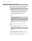
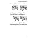
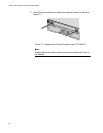
6. To install a new fan, do one of the following:
Caution
Avoid touching the fan blades.
AT-CV5PWRAC
PO
W
E
R
F
A
U
LT
AT-PW
R14
A
B
100-240
V
A
C
~
P
O
W
E
R
F
A
U
LT
A
AT-CVFAN
204
1
0
0
-2
4
0
V
A
C
~
W
A
R
N
I
N
G
This u
nit m
ig
ht ha
ve
more
th
a
n one po
wer input. T
o
reduce the risk of electric s
hock, disconnect a
ll po
wer
AT-PWR14
AT-CV5PWRAC
A
B
1
0
0
-2
4
0
VA
C
~
FA
N
A
B
P
O
W
E
R
F
A
U
L
T
AT-CVFAN
205
1
0
0
-
2
4
0
V
A
C
~
WARNING
T
h
i
s
u
n
it
m
ig
h
t
h
a
v
e
m
o
r
e
t
h
a
n
o
n
e
p
o
w
e
r
in
p
u
t.
T
o
re
d
u
c
e
th
e
r
is
k
o
f
e
le
c
t
r
ic
s
h
o
c
k
, d
is
c
o
n
n
e
c
t a
ll
p
o
w
e
r