


Chapter 1: Overview
22
Data bits: 8
Parity: None
Stop bits: 1
Flow control: None
These default settings are for a DEC VT100 or ANSI terminal, or an
equivalent terminal emulation program.
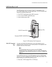
Interface Card
LEDs
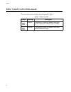
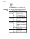
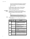
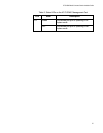
Table 1 lists the system status LEDs located on the LED interface card.
Table 1. Status LEDs on the LED Interface Card
LED State Description
RDY
(For future use)
Green The module installed in the rear
expansion slot has passed
diagnostics and is ready.
OFF The module installed in the rear
expansion slot has failed diagnostics
and is not ready, or is not installed.
MSTR
(For future use)
Green This AT-CV5000 chassis is acting as
a Stacking Master (via a module
installed in the rear expansion slot.)
OFF This AT-CV5000 chassis is not a
Stacking Master.
FLT
(For future use)
Green The module installed in the rear
expansion slot has a fault condition, or
is not installed.
OFF The module installed in the rear
expansion slot has not reported a fault
condition.
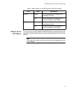
PS-A Green The power supply in slot A is
operating normally.
OFF The power supply in slot A is OFF, not
present, or has failed.
PS-B Green The power supply in slot B is
operating normally.
OFF The power supply in slot B is OFF, not
present, or has failed.