


AT-CV5000 Media Converter Chassis Installation Guide
51
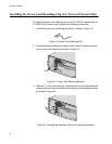
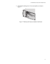
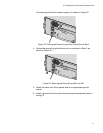
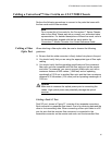
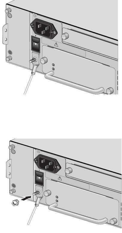
The frame ground stud for power supply A is shown in Figure 22.
Figure 22. Placing the Ground Lug on the Frame Ground Stud
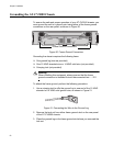
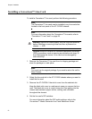
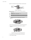
4. Secure the ground lug with the lock nut you removed in Step 2, as
shown in Figure 23.
Figure 23. Securing the Ground Lug with Lock Nut
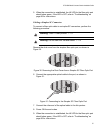
5. Attach the other end of the ground wire to an appropriate ground
(earth).
6. Install a ground wire to the other frame ground stud repeating steps 1
through 5.
POW
ER
F
A
ULT
AT-PWR14
A
100-240
V
AC
~
AT-CVFAN
A
100-240VAC
~
W
ARNING
T
h
is
u
n
it m
ig
h
t h
ave
m
o
re
th
a
n
o
n
e
p
o
w
e
r in
p
u
t
.
T
o
re
d
u
c
e
th
e
ris
k
o
f e
le
c
tric
s
h
o
ck, d
is
c
o
n
n
e
c
t a
ll p
o
w
e
r
in
p
u
ts
b
e
f
o
re
s
e
rv
ic
in
g
u
n
it.
POW
ER
F
A
U
LT
AT-PWR14
A
100-240
V
AC
~
AT-CVFAN
A
100-240VAC
~
W
ARNING
This unit might have more than one power input
.
T
o
reduce the risk of electric shock, disconnect all power
inputs be
f
ore se
rvicing unit.