


26 Thermal Design of Custom 1U-2P Systems Chapter 4
32800 Rev. 3.02 August 2006
Thermal Design Guide for Socket F (1207) Processors
Other fan and heat sink combinations may yield adequate thermal performance. The system designer
must ensure that the thermal solution provides required cooling for the processor for the given system
layout and flow characteristics.
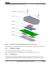
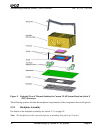
Because the processor-mounting surface extends above the surface of the cam box on the socket, the
heat sink bottom can be flat. The heat sink must have a flat surface of at least 40 mm x 40 mm,
centered over the processor.
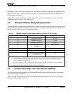
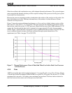
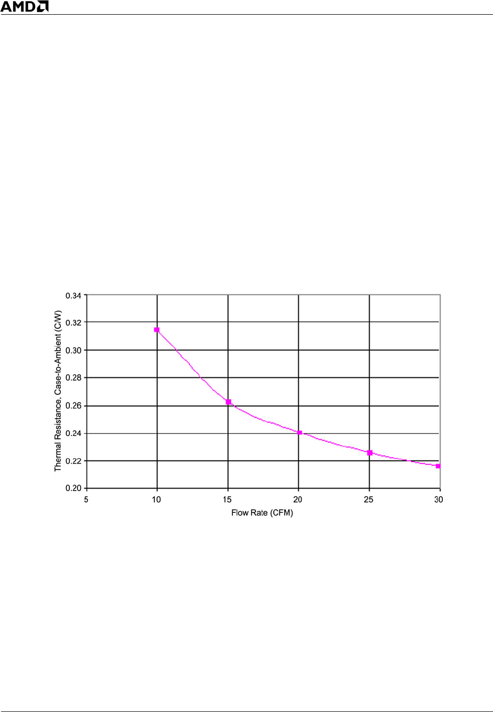
Figure 7 shows the measured thermal performance vs. flow rate for a slightly shorter version of this
heat sink (3.5" hole pitch vs. 4.1" hole pitch). This data represents the expected performance of this
heat sink on a dual-core socket F (1207) processor. Based on flow tests on the AMD reference 1U-2P
system, the flow through the heat sink is estimated to be approximately 20 cubic feet per minute
(CFM). Figure 7 shows that this corresponds to case-to-ambient thermal resistance of 0.24°C/W. This
case-to-ambient thermal resistance has been confirmed through system thermal tests. The
requirement (see Table 4 on page 22) is 0.26°C/W.
Figure 7. Thermal Performance Chart of Heat Sink When Used with a Dual-Core Processor
in 90 nm Process
4.3.4 Fans
AMD has tested the heat sink described in Section 4.3 on page 22 with a row of five 40 mm x 50 mm
x 56 mm fans (Delta Part number GFB0412EHS) in a typical 1U-2P system. The fan has a 27.3-CFM
maximum flow rate and a 1.63-inches water maximum pressure head. The heat sinks are ducted so
the flow from two fans enters each of the processor heat sinks.