


34 Thermal Design of Custom 2U-4P Systems Chapter 5
32800 Rev. 3.00 August 2006
Thermal Design Guide for Socket F (1207) Processors
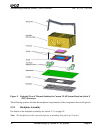
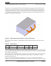
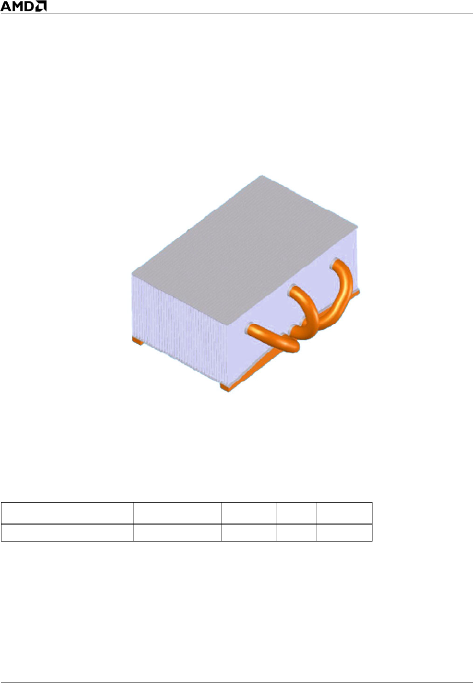
the center to 2.5 mm at the edges. The heat sink also has three heat pipes soldered to the base and
connected to the top of the fin stack to improve fin efficiency. This design provides optimum heat
spreading performance from the processor to the heat sink. The fin geometry has been designed to
provide optimized thermal performance in combination with the fans, as described in Section 5.3.5,
on page 35, in a typical 2U-4P system.
Figure 10. High Performance Heat Sink for Custom 2U-4P Systems
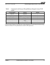
Table 10 shows the parameters of the aluminum fins for the high-performance heat sink shown in
Figure 10.
Other fan and heat sink combinations may yield adequate thermal performance. The system designer
must ensure that the thermal solution provides required cooling for the processor for the given system
layout and flow characteristics.
Because the processor-mounting surface extends above the surface of the cam box on the socket, the
heat sink bottom can be flat. The heat sink must have a flat surface of at least 40 mm x 40 mm,
centered over the processor.
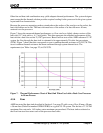
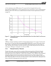
Figure 11 shows the measured thermal performance vs. flow rate for this heat sink. This data
represents the expected performance of this heat sink on a dual-core socket F (1207) processor. Based
Table 10. Fin Parameters
Length Height (at Center) Height (at Edges) Thickness Pitch No of Fins
92 mm 32.5 mm 37 mm 0.2 mm 1.5 mm 39