


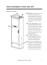
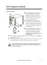
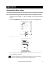

Smart Distribution Panel with ATS
14 InfraStruXure Power Generation System
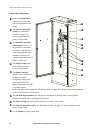
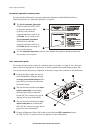
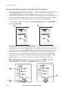
ATS panel board, right side
The Source 1 input switch accepts input wires
from the utility (refer to the Electrical
Installation Manual for connection
instructions).
WARNING: Only a certified electrician
should connect utility power to the ATS!
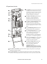
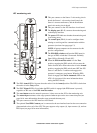
Behind this access panel are the Source 1 volt-
sensing circuit board and the distribution panel
volt-sensing circuit board. Use a Phillips or
standard screwdriver to remove the panel.
The Source 1 current transformers monitor
the input current of each incoming phase from
the utility. The data gathered from these
transformers is displayed on the Total Load by
Phase screen, which is accessed through the
Load Meter menu on the display interface.
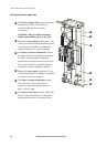
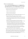
Behind this access panel is the Source 2 volt-
sensing circuit board. Use a Phillips or standard
screwdriver to remove the panel.
The Source 2 control transformer outputs
120 VAC and 18 VAC to the Source 2
motorized switch after stepping down the
480 V or 208 V input.
The Source 2 fuse block regulates input to the
Source 2 control transformer for subsequent
powering of the Source 2 motorized switch.