


InfraStruXure Power Generation System 63
How to Connect an EPO Switch to the ATS
Overview
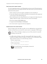
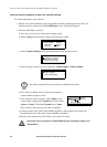
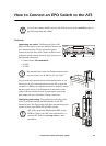
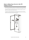
Connecting the switch. The Emergency Power Off
(EPO) switch connects to the user interface board on the
user connection plate. The user connection plate is
located on the roof of the ATS. Connect an EPO switch
to the user interface board (shown at right) using one of
the following connections:
• Contact closure (Recommended!)
•24 VAC
• 24 VDC
You can make this connection from inside the enclosure, or you
can remove the user connection plate from the ATS to make the
connection. A Phillips or standard screwdriver is needed to loosen
the two captive screws. Use the knockout in this plate to route
cables to the user interface board. If you decide to remove the
plate, make sure not to disturb the existing connections.
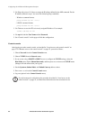
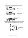
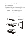
Configuring and testing. The configuring and testing of the
switch is performed through the EPO interface on the ATS
monitoring unit. The figure on the right shows the monitoring unit
and the location of the EPO LEDs and DIP switches.
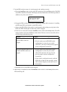
Note
If you do not connect an EPO switch to the ATS, be sure to set the Arm/Test rocker on
the ATS monitoring unit to Test.
Note
The terminal block on the user interface board accepts
wire sizes from 12 to 30 AWG or 2.5 to 0.2 mm
2
.
Note
APC offers an optional InfraStruXure EPO System
(EPW9). Contact your APC sales representative, or
visit the APC Web site (www.apc.com) for more
information.
1 234
ATS EN
ATS 0
ATS 1
ATS 2
EPO
Contact
–
+
EPO 24V
AC/DC
Contact Inputs
Contact Outputs
USER INTERFACE
© 2001 APC
MADE IN USA
NO NC
USER / EPO CONTACTSTO UPS
DISPLAY
10=G RN
100=ORN
NETWORK
POWER
RS-232
CONSOLE PORT
9600-8 -N-1
RESET
TRIPPED
STATUS
LINK RX/TX
ARMED
TEST
EPO
885-2288
12345678910111213
25242322 21 2019 1817 1615 14
NO
NC
TRIPPED
ARMED
TEST
EPO