


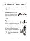
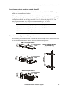

How to Connect an EPO Switch to the ATS
InfraStruXure Power Generation System 65
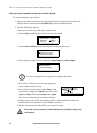
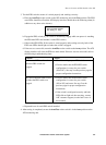
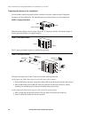
3. Test the EPO switch to ensure it is wired properly and working correctly:
a. Place the Arm/Test rocker switch on the ATS monitoring unit in the Test position. The EPO
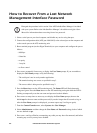
state LEDs should be off and the ATS display interface should show the following alarm (in
addition to any other active alarms):
b. Engage the EPO switch (if your switch is momentary, engage while one person is watching
the EPO state LEDs and another is at the EPO switch).
c. Observe the EPO LEDs. If the switch is wired properly and working correctly, both of the
EPO state LEDs should light red when the switch is engaged.
d. If the test was successful, return the Arm/Test rocker switch to the Arm position. The ATS
display interface will clear the EPO test mode alarm. If the test was not successful, refer to
the following troubleshooting chart:
e. Repeat this test for each EPO switch installed.
4. After testing is completed, ensure the Arm/Test rocker switch is in the Arm position on the
ATS monitoring unit.
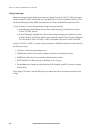
Problem Action
Neither state LED was lit red
when the EPO switch was
engaged.
• Check the wiring to your EPO switch.
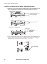
• Check to make sure the EPO DIP switch
configuration is correct for your switch
(NO or NC). See step 2 on the previous page for
proper configuration instructions.
Only one of the state LEDs was lit
red when the EPO switch was
engaged.
• Check to make sure the EPO DIP switch
configuration is correct for your switch
(NO or NC) and retest. See step 2 on the
previous page for proper configuration
instructions.
• If the switch is configured correctly and both
LEDs did not light red after retesting, contact
APC customer support (see the back cover of
this manual).
EPO Ready To Test
Active Alarm xxofxx