


MX28B200/400 –48 VDC User’s Manual (990-9133) Page 15
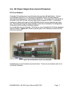
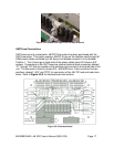
GMT Fuse Installation
Fuse holders that accommodate GMT fuses are located on the interface card mounted in
the top left side of the unit. Insert the fuse in the holder; observing the tripped indicator is
correctly oriented. These fuse holders are only connected to -48VDC if the system has
been purchased with the GMT fuse option. This option supplies -48VDC to lugs on the
interface card through a 50 Amp circuit breaker located in circuit breaker Position 1. The
interface card provides fuse holders for eight fuses, labeled “F1” through “F8”, which can
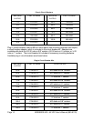
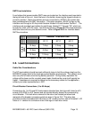
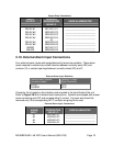
be used for small -48V DC loads. Use the chart shown in Figure 3.7-2 to help determine
what size fuses will carry the desired current. Refer to Figure 3.8-3 for Interface board
GMT fuse locations.
AMBIENT TEMPERATURE
20° C 50° C 60° C
10 Amp 7 Amp 6 Amp 5 Amp
12 Amp 8 Amp 7 Amp 6 Amp
FUSE
SIZE
15 Amp 10 Amp 9 Amp 8 Amp
Figure 3.7-2 GMT Fuse Temperature De-rating Chart
3.8. Load Connections
Cable Size Considerations
The DC load cable(s) should be sized sufficiently large to limit the voltage drop from the
MX28B DC power plant to the loads per system design requirements. The cable(s) must
also carry the full load current during battery operation. During battery operation the
voltage will be lower and for constant power loads, therefore the current will typically be
higher. If assistance is required to determine the necessary cables for the application,
contact your sales representative or APC.
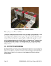
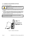
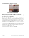
Circuit Breaker Connections (1 to 50 Amps)
Connections for 1 to 50 amp DC loads require standard two-hole lugs with holes for #10
screws (810-0032) on 5/8” centers and are located directly above the corresponding
circuit breaker. The load returns connect to the return bus located just above and
rearward of the breaker connection points as seen in Figure 3.8-1 The return bus
provides 24 sets of threaded #10-32 holes on 5/8” centers and four sets of threaded ¼-20
holes on ¾” centers for connection of two-hole lugs on load return wires.