


Page 18 MX28B200/400 –48 VDC User’s Manual (990-9133)
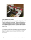
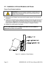
3.9. Monitoring and Relay Output Connections
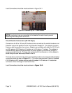
Front Panel DB9 Connection
The front panel DB-9 connector is used to hook up a standard serial cable for the APC
proprietary GUI that will be introduced at a later date. Do not hook up the special RS-232
cable (APC part number 940-0024C). This cable is only to be used with the DB-9 near
the Web/SNMP card.
“Smart” Cable DB9 Connection
The DB9 connector on the top right hand side of the unit uses the special RS-232 cable
(APC part number 940-0024C) to allow local access through a Terminal Emulation
program like HyperTerminal™ or Procomm™ (**).
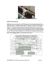
RJ45 Ethernet Connector
The optional management card has an RJ-45 connector to support a TCP/IP protocol
over a 10BaseT Ethernet Local Area Network (LAN).
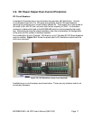
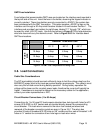
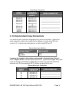
Relay Output Connections
There are eight alarms available that provide outputs via Form “C” relay contacts. The
last two of these are preassigned as the Minor and Major relay outputs. The Major relay
is energized (NO-C contacts closed) during normal (non-alarm) operating conditions; all
the other relays energize when an alarm condition occurs. The other six outputs are
initially designated as “Relay 1” through “Relay 6” (the user may assign more meaningful
names if desired). The various system alarm conditions can be assigned to any of the
eight alarm outputs. Connectors J1 and J2 are located on the interface card mounted in
the top left side of the unit. Refer to the board layout in Figure 3.8-3 for Output Relay
connections. The relay contacts should only be used to switch resistive loads of 0.5
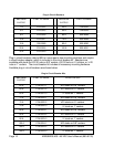
amperes or less at 60 volts or less. The following shows the alarm output connection
designations.