


Page 26 MX28B200/400 –48 VDC User’s Manual (990-9133)
batteries, possible thermal runaway. Battery Maximum Recharge Current is set to the
appropriate rate, which is usually based on the size of the battery plant in Ampere-hours.
A typical recharge current setting is battery capacity (abbreviated as “C”) divided by
number of charging hours. As an example, a “C/10” rate will basically return the battery
to full charge in 10 hours. A C/8 rate is probably the highest current, which should be
considered for charging under normal circumstances.
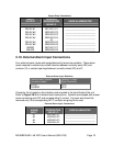
Battery Temperature Compensation
The Battery Float Voltage is set to the value recommended by the battery manufacturer
in order to maintain correct battery charge at 25ºC. As temperature rises,
electrochemical activity in a battery increases. Similarly, as temperature falls,
electrochemical activity in a battery decreases. As temperature rises charging voltage
should be reduced to prevent overcharge and increased as temperature falls to prevent
undercharge. The DC power system uses Battery Temperature compensation to change
output voltage to compensate for temperature changes. This temperature compensation
function is programmed into the PSCU using the compensation parameters settings.
Default settings can be changed to values recommended by the particular battery
manufacturer.
Battery/Load Low Voltage Disconnect
In order to prevent damage to the battery due to deep discharge, the DC power system
has hardware and software support for a battery or load Low Voltage Disconnect (LVD).
A battery LVD has the loads permanently attached to the rectifiers and the battery is
disconnected from the system. A load LVD has the battery permanently attached to the
rectifiers and the loads are disconnected from the system.
When the battery voltage reaches the threshold set by the LVD 1 Trip Voltage setting
during discharge, the DC power system will activate the LVD contactor to disconnect the
battery or load from the system. The LVD will remain open until AC power is restored to
the system and the bus voltage reaches the level defined by the LVD 1 Reset Voltage
variable.
NOTE: The LVD is normally energized and must be commanded to open. This
assures that the LVD will remain closed even if the controller fails or is removed.
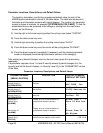
4.6. Controls and Indicators
Front Panel User Interface
The MX28B control unit provides a user interface designed with a hierarchical menu that
can be viewed on the 32-character (2 X 16) display by “navigating” with the “ï” (left), “ð”