


Page 42 MX28B200/400 –48 VDC User’s Manual (990-9133)
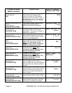
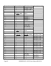
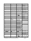
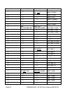
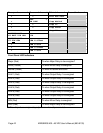
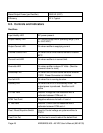
Top Level Second Level
Third Level Fourth Level
• •
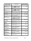
Batt Max Rech
•
BAT: +
AM COMP
Comp Method
• •
Comp TC
• •
Comp HKnee
• •
Comp LKnee
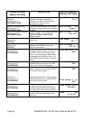
MX28B200/400 +
ES BATT PIN OEM
PIN
MX28B200/400 +
TT PIN OEM
OEM R Offset
•
OEM R Gain
•
OEM S Offset
•
OEM S Gain
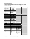
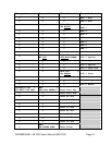
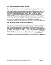
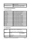
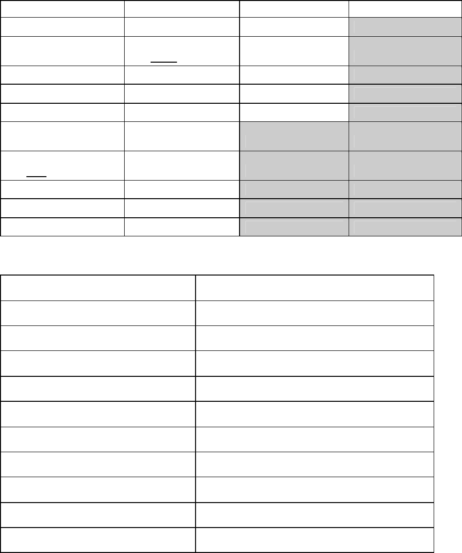
Front Panel LED Indicators
Major (Red) On when Major Relay is de-energized*
Minor (Yellow) On when Minor Relay is energized
Normal (Green) On when no alarms are active
ALM 1 (Red) On when Output Relay 1 is energized
ALM 2 (Red) On when Output Relay 2 is energized
ALM 3 (Red) On when Output Relay 3 is energized
ALM 4 (Red) On when Output Relay 4 is energized
ALM 5 (Red) On when Output Relay 5 is energized
ALM 6 (Red) On when Output Relay 6 is energized
MIN (Red) On when Minor Relay is energized
MAJ (Red) On when Major Relay is de-energized*
* This will produce a major relay output even when all power is lost.