


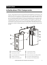
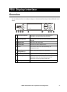

Overview: InfraStruXure PDU
10 150kW InfraStruXure PDU—Operation and Configuration
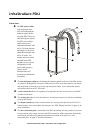
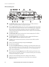
PDU monitoring unit
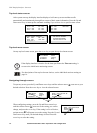
The EPO DIP switches configure the EPO input for the type of EPO switch that is
connected—Normally Open (NO) or Normally Closed (NC).
When the EPO Arm/Test rocker is in the Test position, engaging the EPO switch will not
cause the load to be powered off. When the rocker is in the Armed position, engaging the
EPO switch will cause the PDU’s main input switch to be switched OFF. See “How to
Connect an EPO Switch to the PDU and Test the Switch” on page 56 for more information
on testing the EPO switch.
The EPO Armed LED is green when the rocker is in the Armed position. The LED is
dark when the rocker is in the Test position.
The EPO Tripped LED is red when the EPO switch is engaged (the EPO button is
pressed), regardless of the state of the EPO Arm/Test rocker.
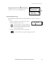
The Reset button resets the network processor; it does not reset the PDU or the PDU
monitoring unit.
Connect to the InfraStruXure Manager through the network port.
Not used in this model PDU.
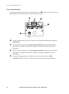
The optional User/EPO Contacts port is connected to wire harnesses that connect to the
User Connection Plate in the roof (or floor) of the PDU. The port allows for four (4) relay
outputs, four (4) input contacts, and one (1) EPO input. See “User connection plate” on
page 12 for more information.
This connection provides the input power for the PDU monitoring unit from the circuit
breaker on the front of the PDU. If the panel is on, and the monitoring unit circuit breaker
is closed, the monitoring unit is powered.
Connects to sensors monitoring values such as voltage, current, and power.
Digital input sensing for monitoring such as circuit breaker status, transformer
temperature, fans, etc.