


150kW InfraStruXure PDU—Operation and Configuration 59
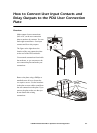
How to Connect an EPO Switch to the PDU
and Test the Switch
Overview
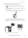
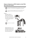
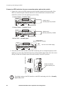
Connecting the switch. The
Emergency Power Off (EPO) switch
connects to the PDU user connection
plate. The figure on the right shows the
location of the user connection plate on the
roof of the PDU. Connect a switch using
one of the three following connections:
• Contact closure
•24VAC
•24VDC
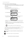
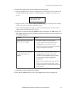
Configuring and testing. Configuring
and testing of the switch is done through
the EPO interface on the PDU monitoring
unit. The figure to the right shows the
PDU monitoring unit and the location of
the EPO LEDs and DIP switches.
Note
APC offers an optional InfraStruXure EPO System (EPW9). Contact your APC sales
representative, or visit the APC Web site (www.apc.com) for more information.
Caution
If you are not connecting an Emergency Power Off switch to the PDU, leave the
Arm/Test rocker switch on the PDU monitoring unit in the Test position.
Note
Contact closure is recommended.
1 234
ATS E N
ATS 0
ATS 1
ATS 2
EPO
Contact
– +
EPO 24 V
AC/D C
Contact Inputs
Contact Outputs
USER INTERFACE
© 2001 APC
MADE IN USA