


Overview
60kW InfraStruXure PDU—Operation and Configuration 25
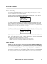
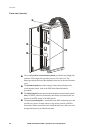
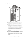
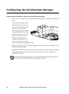
Rear view of PDU with transformer (interior)
The Main input switch connects to your main power source. The
switch accepts 400V input and requires L1, L2, L3, and PE input
conductors.
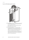
The PDU monitoring unit has several current and voltage monitoring
boards that report to a central board assembly located in the PDU
monitoring unit. The PDU monitoring unit has one 10BaseT (Cat-5)
connection to the Information Controller hub (or switch), four relay
output connections, four input contact connections, and one EPO input
connection. Make these connections at the user connection plate
located on the roof of the PDU. See “PDU monitoring unit” on
page 27 and “User connection plate” on page 28 for a more detailed
description.
The output of the optional isolation input transformer feeds the input
circuit breaker of the maintenance bypass panel.
Note: The secondary side of the optional isolation/input transformer
should be provided with a suitable separate connection to an earth
electrode.