


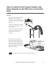


Customizing and Updating the PDU
60kW InfraStruXure PDU—Operation and Configuration 51
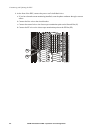
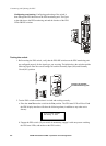
c. Observe the EPO LEDs. If the switch is wired and working properly, when the switch is
engaged, both of the EPO state LEDs are red.
d. If the test was successful, place the Arm/Test rocker switch back to the Arm position. The
PDU display interface will clear the EPO test mode alarm. If the test was not successful, see
the troubleshooting chart:
e. Repeat this test for each EPO switch installed.
3. Ensure that the Arm/Test rocker switch is in the Arm position on the monitoring unit.
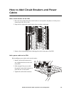
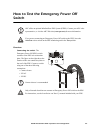
Emergency Power Off (EPO)
This InfraStruXure PDU is provided with an Emergency Power Off switch connection. When this
EPO switch is energized, electrical power to the units is de-energized and the system will not transfer
to on-battery operation.
EPO can be achieved with either a contact closure or application of an external 24VAC or 24VDC
from a SELV or PELV source. It’s important to note that hazardous voltage from the Mains voltage
must be isolated from the contact closure or 24 VAC, 24 VDC. The EPO circuit contact closure, the
24VAC or the 24VDC are considered a SELV circuit as defined in EN 60950 Safety of Information
Technology Equipment or PELV circuit as defined in IEC 60364-4-41 Electrical Installations of
Buildings, Protection for Safety—Protection Against Electric Shock. SELV is an abbreviation for
Safety Extra Low Voltage. PELV is an abbreviation for Protective Extra Low Voltage. SELV and
PELV circuits are isolated from the Mains through a safety isolating transformer, and are designed so
that under normal conditions the voltage is limited to 42.4 Vpeak or 60VDC.
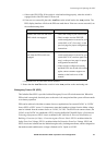
Problem Action
Neither state LED was red when
EPO switch was engaged
• Check the wiring to your EPO switch.
• Check to make sure the EPO DIP
switch configuration is correct for your
switch (NO or NC). See step 1 on the
previous page for proper configuration
instructions.
Only one of the state LEDs was
red when the EPO switch was
engaged
• Check to make sure the EPO DIP
switch configuration is correct for your
switch (NO or NC) and test again. See
step 1 on the previous page for proper
configuration instructions.
• If the switch is configured correctly
and both LEDs are not red after testing
again, contact customer support at a
number on the back cover of this
manual.