


Customizing and Updating the PDU
50 60kW InfraStruXure PDU—Operation and Configuration
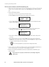
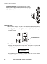
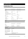
Configuring and testing. Configuring and testing of the switch is
done through the EPO interface on the PDU monitoring unit. The figure
to the right shows the PDU monitoring unit and the location of the EPO
LEDs and DIP switches.
Testing the switch
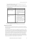
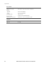
1. Before testing the EPO switch, verify that the EPO DIP switches on the PDU monitoring unit
are configured properly for the signal type you are using. The labels above the switches and the
following figure show the correct settings for both the Normally Open (NO) and Normally
Closed (NC) position.
2. Test the EPO switch to ensure that it is wired and working correctly:
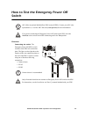
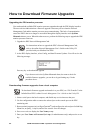
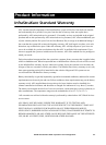
a. Place the Arm/Test rocker switch in the Test position. The EPO state LEDs will be off and
the PDU display interface will show the following alarm (in addition to any other active
alarms):
b. Engage the EPO switch. (If your switch is momentary, engage it with one person watching
the EPO state LEDs, and another at the EPO switch.)
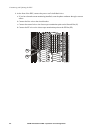
Location of switches
on PDU monitoring unit
Active Alarm xxofxx
EPO Ready to Test