


Overview
60kW InfraStruXure PDU—Operation and Configuration 27
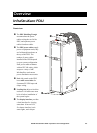
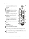
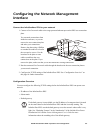
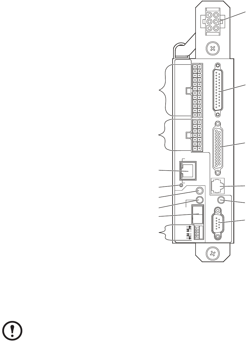
PDU monitoring unit
This connection provides the input power for the PDU
monitoring unit. The power is supplied by the monitoring unit
circuit breaker on the front of the PDU. If the panel is on, and
the monitoring unit circuit breaker is closed, the monitoring
unit is powered.
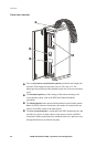
Connects to sensors monitoring values such as voltage, current,
and power.
Digital input sensing for monitoring such as circuit breaker
status, transformer temperature, fans, etc.
The Display port (RJ-45) connects the PDU monitoring unit to
the PDU display interface.
The Power LED indicates whether the monitoring unit is
receiving power.
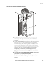
Use the Console port (DB-9) to connect a laptop computer to
the monitoring unit using an appropriate communication cable
(APC part number 940-0103). This port is used to configure
items relating to servicing the PDU.
EPO DIP switches configure the EPO input for the type of
EPO switch that is connected—Normally Open (NO) or
Normally Closed (NC).
When the EPO Arm/Test rocker is in the Test position,
engaging the EPO switch will not cause the load to be powered
off. When the rocker is in the Armed position, engaging the
EPO switch will cause the PDU’s main input switch to be
switched OFF. See “How to Test the Emergency Power Off
Switch” on page 49 for more information on testing the EPO
switch.
The EPO Armed LED is green when the rocker switch is in the
Armed position. The LED is dark when the rocker is in the Test
position.
The EPO Tripped LED is red when the EPO switch is engaged
(the EPO button is pressed), regardless of the state of the EPO
Arm/Test rocker switch,
The Reset button resets the network processor; it does not
reset the PDU or PDU monitoring unit.
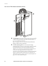
Connect to the InfraStruXure Manager through the network port.
Not used on this model PDU.
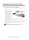
The optional User/EPO Contacts port is connected to wire harnesses that connect the User Connection Plate in the
roof (or floor) of the PDU. The port allows for relay outputs (4), input contacts (4), and an EPO input (1). See
“Contacts Screen” on page 10 and “How to Test the Emergency Power Off Switch” on page 49 for more
information.
Note
The branch current monitoring boards connect to the Branch Current Monitor ports (RJ-11). These ports
are on the top side of the PDU monitoring unit, and are labeled on the face of the unit. Each port corresponds
to a section of circuit breakers on the PDU distribution circuit breaker panel: upper left=[01..41]; upper
right=[02..42]; lower left=[43..83]; lower right=[44..84].
NO
NC
USER / EPO CONTACTS
TO UPS
DISPLAY
10=GRN
100=ORN
NETWORK
POWER
RS-232
CONSOLE PORT
9600-8-N-1
RESET
TRIPPED
STATUS
LINK RX/TX
ARMED
TEST
EPO
885-2288
12345678910111213
25 24 23 22 21 20 19 18 17 16 15 14