


Fastmark 600 Series User's Guide 8
TABLE OF FIGURES
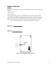
Figure 1 – Model and Serial Number Location........................................................................10
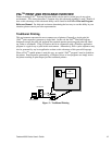
Figure 2 – Traditional Printing...............................................................................................12
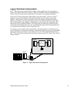
Figure 3 – Legacy Data stream Interpretation..........................................................................13
Figure 4 – Shipped with Printer .............................................................................................14
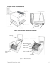
Figure 5 – External Switches, Indicators and Connections .......................................................16
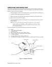
Figure 6 – Internal Features...................................................................................................16
Figure 7 – Power Connection.................................................................................................17
Figure 8 – Communication Cable...........................................................................................18
Figure 9 – Top Media Cover Latches.....................................................................................19
Figure 10 – Print Head Latches .............................................................................................19
Figure 11 – Ribbon Holder Notches and Ribbon Core Slots....................................................20
Figure 12 – Supply Ribbon Installation...................................................................................21
Figure 13 – Ribbon Take-Up Installation................................................................................22
Figure 14 – Ribbon Installation..............................................................................................22
Figure 15 – Print head Module Closed....................................................................................23
Figure 16 – Top Media Cover Latches...................................................................................24
Figure 17 – Media Roll Installation........................................................................................24
Figure 18 – Print Head Latches .............................................................................................25
Figure 19 – Media Sensor and Guides....................................................................................25
Figure 20 – Loading Media over Platen Roller........................................................................26
Figure 21 – Positioning Media Guides and Sensor ..................................................................26
Figure 22 – Print head Module Closed....................................................................................27
Figure 23 – Label Removal for Peeler Option.........................................................................28
Figure 24 – Straight Edge and Peeler Latch............................................................................28
Figure 25 – Feeding into the Peeler Mechanism......................................................................29
Figure 26 – Backing Exit Position..........................................................................................29
Figure 27 – Peeler Option......................................................................................................30
Figure 28 – Inserting Labels in the Cutter Option....................................................................31
Figure 29 – Cutting Labels ....................................................................................................31
Figure 30 – Calibration of the Media ......................................................................................32
Figure 31 – Configuration Print Sample .................................................................................33
Figure 32 – Fastmark 600 Series Front Panel..........................................................................34
Figure 33 – FeatureMan Program..........................................................................................36
Figure 34 – Changing Features..............................................................................................37
Figure 35 – Changing Feature Values ....................................................................................37
Figure 36 – Print Head Location ............................................................................................78
Figure 37 – Platen Roller and Media Sensor ...........................................................................79