


Installation
10
NXR-ZGW/-ZRP
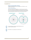
Connecting the Optional Accessory Antennas
Several accessory 2.4GHz antennas are available for use with NXR-ZGW and NXR-ZRP devices. Each
of these antennas is uniquely suited to meet a wide variety of installation requirements.
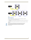
Determining the Power Source
Based upon location and the availability of electricity, select one of the two following methods for
power:
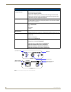
2-pin 3.5mm captive-wire connector - Prepare the captive wire pair and insert it into the
connector. See Preparing captive wires for the 2-pin 3.5 mm mini-captive wire
connector section on page 10. This is the only power option for the NXR-ZRP device.
Power Over Ethernet (PoE) - If no electrical outlet is available, you can plug one end of the
CAT5 Ethernet cable into the RJ-45 jack of the NXR-ZGW and plug the other end of the
CAT5 cable into PoE supply equipment (this unit must be 802.3af compliant). The
NXR-ZGW is rated as a PoE Class 2 device that consumes about 2.5W, about 50mA to 60mA
at 48V.
The ability to choose a power supply option increases the availability of deployment locations. In
addition, the NXR-ZGW makes installation into areas previously without power much easier, since it is
no longer necessary to run new electrical wires to the device.
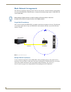
Connecting the NXR-ZGW to a LAN
Insert one end of the CAT5 Ethernet cable into the rear RJ-45 jack (illustrated in FIG. 1) and connect the
other end of the same cable to a master. See Mesh Network Arrangements section on page 6 for possible
network configurations.
Connecting Power to the NXR-ZGW and NXR-ZRP
The NXR-ZGW receives power via either PoE or 2-pin 3.5 mm mini-captive wire connection, while the
NXR-ZRP only utilizes the 2-pin 3.5 mm mini-captive wire connection.
If PoE is selected, the NXR-ZGW will draw power through the CAT5 Ethernet cable (see Determining
the Power Source section on page 10). If the 2-pin 3.5 mm mini-captive wire is selected, the following
steps are necessary:
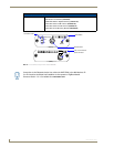
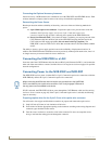
Preparing captive wires for the 2-pin 3.5 mm mini-captive wire connector
You will need a wire stripper and flat-blade screwdriver to prepare and connect the captive wires.
1. Strip 0.25 inch (6.35 mm) of wire insulation off all wires.
2. Insert each wire into the appropriate opening on the connector according to the wiring diagrams and
connector types described in this section.
3. Turn the screws clockwise to secure the wires in the connector. Do not over-torque the screws;
doing so can bend the seating pins and damage the connector.
When connecting both Ethernet and mini-captive wire connections to the NXR-ZGW,
PoE is overridden by the captive wire connection. PoE is only engaged if Ethernet is
the only power source available to the device.