


Installation
11
NXR-ZGW/-ZRP
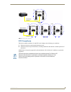
Using the PSN NetLinx connector for power
The PWR and GND cable from the 12 VDC power supply must be connected to the corresponding
location on the 2-pin 3.5 mm mini-captive wire connector (FIG. 6).
1. Insert the PWR and GND wires on the terminal end of a PSN 2-pin 3.5 mm mini-captive wire cable.
Match the wiring locations of the +/- on both the power supply and the terminal connector.
2. Tighten the clamp to secure the two wires. Do not over-torque the screws; doing so may strip the
threads and damage the connector.
3. Verify the connection of the 2-pin 3.5 mm mini-captive wire to the power supply.
Table top installation of the NXR-ZGW and NXR-ZRP
Using the provided rubber pads, place one in each bottom corner of the device.
Rack mounting the NXR-ZGW and NXR-ZRP
Using the Velcro pad provided, remove the backing and adhere one side to the device. Remove the
backing of the other side of the Velcro and place it on your rack where you want the NXR-ZGW/ZRP
mounted.
Before continuing, consult Setting up a Network section on page 13.
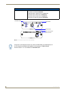
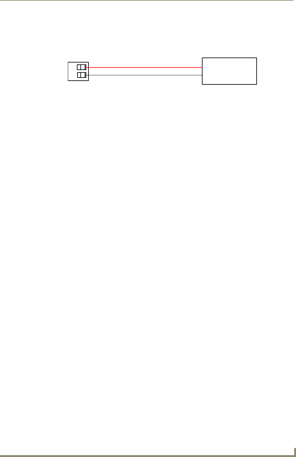
FIG. 6 12 VDC Power Connector Wiring Diagram
PWR +
GND -
To the Device
12 VDC Power Supply