


REV. B
ADuC812
–24–
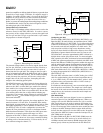
WATCHDOG TIMER
The purpose of the watchdog timer is to generate a device reset
within a reasonable amount of time if the ADuC812 enters
an erroneous state, possibly due to a programming error.
The Watchdog function can be disabled by clearing the WDE
(Watchdog Enable) bit in the Watchdog Control (WDCON)
SFR. When enabled, the watchdog circuit will generate a system
reset if the user program fails to set the watchdog timer refresh
bits (WDR1, WDR2) within a predetermined amount of time
(see PRE2–0 bits in WDCON).
The watchdog timer itself is a 16-bit counter. The watchdog
timeout interval can be adjusted via the PRE2–0 bits in
WDCON. Full Control and Status of the watchdog timer
function can be controlled via the watchdog timer control
SFR (WDCON).
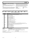
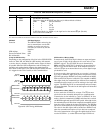
WDCON Watchdog Timer Control Register
SFR Address C0H
Power-On Default Value 00H
Bit Addressable Yes
2ERP1ERP0ERP—1RDW2RDWSDWEDW
Table IX. WDCON SFR Bit Designations
Bit Name Description
7 PRE2 Watchdog Timer Prescale Bits.
6 PRE1
5 PRE0
PRE2 PRE1 PRE0 Timeout Period (ms)
000 16
001 32
010 64
011 128
100 256
101 512
1 1 0 1024
1 1 1 2048
4 — Not Used.
3 WDR1 Watchdog timer refresh bits, set sequentially to refresh the watchdog.
2 WDR2
1 WDS Watchdog Status Bit.
Set by the Watchdog Controller to indicate that a watchdog timeout has occurred.
Cleared by writing a “0” or by an external hardware reset. It is not cleared by a watchdog reset.
1 WDE Watchdog Enable Bit.
Set by user to enable the watchdog and clear its counters.
Example
To set up the watchdog timer for a timeout period
of 2048 ms the following code would be used.
MOV WDCON,#0E0h ;2.048 second
;timeout period
SETB WDE ;enable watchdog timer
In order to prevent the watchdog timer timing out the timer
refresh bits need to be set before 2.048 seconds has elapsed.
SETB WDR1 ;refresh watchdog timer..
SETB WDR2 ; ..bits must be set in this
;order