


REV. B
ADuC812
–37–
Timer 1 Generated Baud Rates
When Timer 1 is used as the baud rate generator, the baud rates
in Modes 1 and 3 are determined by the Timer 1 overflow rate and
the value of SMOD as follows:
Modes 1 and 3 Baud Rate =
(2
SMOD
/32)
× (Timer 1 Overflow Rate)
The Timer 1 interrupt should be disabled in this application. The
Timer itself can be configured for either timer or counter opera-
tion, and in any of its three running modes. In the most typical
application, it is configured for timer operation, in the Autoreload
mode (high nibble of TMOD = 0010 Binary). In that case, the baud
rate is given by the formula:
Modes 1 and 3 Baud Rate =
(2
SMOD
/32)
× (Core Clock/(12
× [256-TH1]))
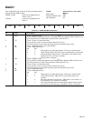
Table XXI shows some commonly-used baud rates and how they
might be calculated from a core clock frequency of 11.0592 MHz
and 12 MHz. Generally speaking, a 5% error is tolerable
using asynchronous (start/stop) communications.
Table XXI. Commonly-Used Baud Rates, Timer 1
Ideal Core SMOD TH1-Reload Actual %
Baud CLK Value Value Baud Error
9600 12 1 –7 (F9h) 8929 7
19200 11.0592 1 –3 (FDh) 19200 0
9600 11.0592 0 –3 (FDh) 9600 0
2400 11.0592 0 –12(F4h) 2400 0
Timer 2 Generated Baud Rates
Baud rates can also be generated using Timer 2. Using Timer 2
is similar to using Timer 1 in that the timer must overflow 16 times
before a bit is transmitted/received. Because Timer 2 has a 16-bit
Autoreload mode a wider range of baud rates is possible using
Timer 2.
Modes 1 and 3 Baud Rate = (1/16) × (Timer 2 Overflow Rate)
Therefore, when Timer 2 is used to generate baud rates, the timer
increments every two clock cycles and not every core machine
cycle as before. Hence, it increments six times faster than Timer
1, and therefore baud rates six times faster are possible. Because
Timer 2 has 16-bit autoreload capability, very low baud rates
are still possible.
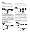
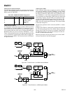
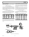
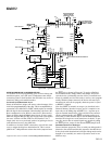
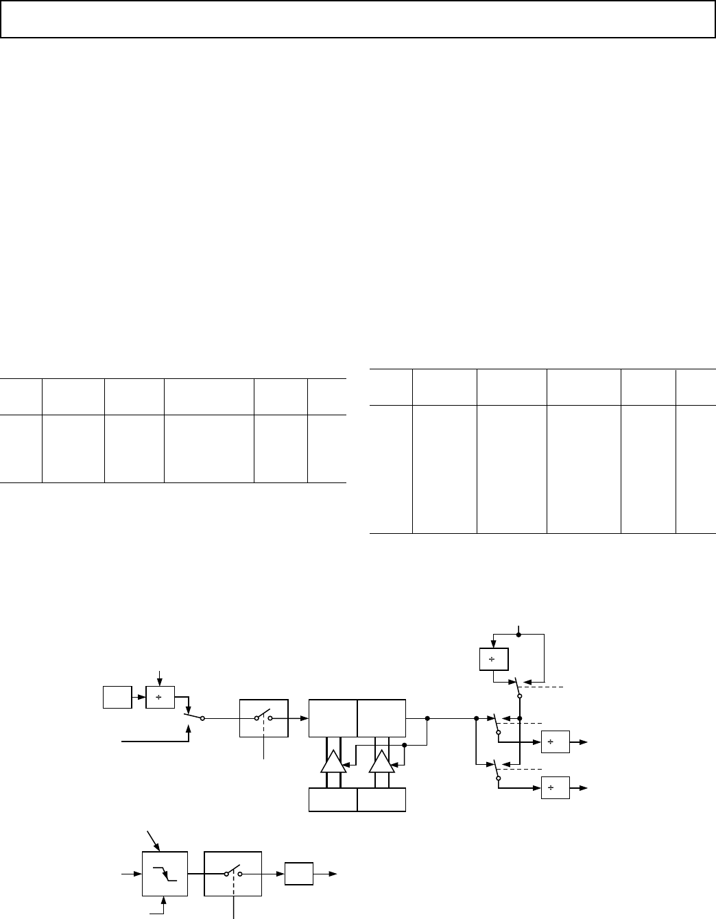
Timer 2 is selected as the baud rate generator by setting the TCLK
and/or RCLK in T2CON. The baud rates for transmit and receive
can be simultaneously different. Setting RCLK and/or TCLK puts
Timer 2 into its baud rate generator mode as shown in Figure 34.
In this case, the baud rate is given by the formula:
Modes 1 and 3 Baud Rate -
(Core Clk)/(32 × [65536 – (RCAP2H, RCAP2L)])
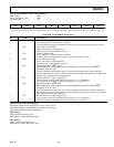
Table XXII shows some commonly used baud rates and how they
might be calculated from a core clock frequency of 11.0592 MHz
and 12 MHz.
Table XXII. Commonly Used Baud Rates, Timer 2
Ideal Core RCAP2H RCAP2L Actual %
Baud CLK Value Value Baud Error
19200 12 –1 (FFh) –20 (ECh) 19661 2.4
9600 12 –1 (FFh) –41 (D7h) 9591 0.1
2400 12 –1 (FFh) –164 (5Ch) 2398 0.1
1200 12 –2 (FEh) –72 (B8h) 1199 0.1
19200 11.0592 –1 (FFh) –18 (EEh) 19200 0
9600 11.0592 –1 (FFh) –36 (DCh) 9600 0
2400 11.0592 –1 (FFh) –144(70h) 2400 0
1200 11.0592 –2 (FFh) –32 (E0h) 1200 0
CORE
CLK
2
T2
PIN
TR2
CONTROL
TL2
(8-BITS)
TH2
(8-BITS)
RELOAD
EXEN2
CONTROL
T2EX
PIN
RCAP2L RCAP2H
NOTE: OSC. FREQ. IS DIVIDED BY 2, NOT 12.
TIMER 2
OVERFLOW
2
16
16
RCLK
TCLK
RX
CLOCK
TX
CLOCK
0
0
1
1
10
SMOD
TIMER 1
OVERFLOW
TRANSITION
DETECTOR
EXF
2
TIMER 2
INTERRUPT
NOTE: AVAILABILITY OF ADDITIONAL
EXTERNAL INTERRUPT
C/T2 = 0
C/T2 = 1
Figure 34. Timer 2, UART Baud Rates