


12 - E-51028230XT/BG
Operation with an
engine generator set
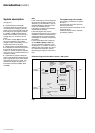
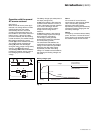
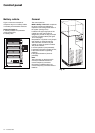
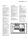
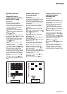
See figure 15 below.
If a stand-by generator is included in
the installation, it is generally started
automatically in the event of a normal
AC source failure and connected to the
main low voltage switchboard. It is
disconnected when normal AC source
power is restored.
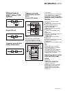
With such a system, the required
battery time may be reduced to the time
necessary for starting and bringing on
line the stand-by generator. The battery
(D) supplies power to the inverter (B)
during the transfers:
◗ normal AC source to the generator;
◗ generator to the normal AC source.
The transfer sequences described
above (normal AC source ➜ battery,
battery ➜ generator, generator ➜
battery, and battery ➜ normal AC
source) are fully automatic. They in no
way affect the load and require no
manual operation by the user.
Note:
To avoid load surges on the generator,
the rectifier/charger is started with a 10
second maximum current consumption
walk-in (lasting 3 to 10 seconds,
depending on the percent load).
To avoid overloading an undersized
engine generator set, it is possible to
set a maximum power level drawn by
the normal AC input. Any additional
power required is supplied by the
battery. This modification can be made
on site by an APC by Schneider
Electric technician.
Fig. 15
Example of an installation with an engine generator set
Introduction (cont.)
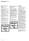
Output voltage quality
and continuity
The output voltage is stable in
amplitude and frequency and is free of
interruptions or transients outside
specified tolerances, irrespective of
normal AC source or load disturbances
(outages, load step changes, etc.).
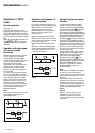
Steady state voltage
regulation
For stable or slowly varying load
conditions, the inverter output voltage is
regulated to within ±0.5% in amplitude.
The frequency of the output voltage can
theoretically be regulated to within
0.1% of the rated value, however the
output frequency range may be
intentionally extended to a maximum of
±2 Hz so that the inverter can remain
synchronised with the bypass AC
source and its inherent frequency
fluctuations, thus enabling transfer of
the load to the bypass line at any time.
Note:
The output frequency range can be
personalised and if necessary modified
on the customer site by a qualified APC
by Schneider Electric support
technician from ±0.25 Hz to ±2 Hz in
0.25 HZ steps.
When the bypass AC source voltage
moves outside this frequency range,
the inverter is desynchronised and
operates in "free running" mode, with
the output frequency regulated to a
high level of accuracy by a quartz
oscillator.
When the bypass AC source frequency
returns to within the specified
tolerances, the inverter is gradually re-
synchronised to the bypass line at a
rate of 0.5 Hz to 2 Hz/s (as per the
value personalised by the after-sales
support department), thus avoiding
exposing the load to sudden frequency
variations.
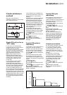
Transient voltage
regulation
The inverter output voltage is not
notably affected by instantaneous
major variations in load characteristics.
This is made possible by the PWM
(Pulse Width Modulation) chopping
technique and the microprocessor-
based regulation system that instantly
compensates for any variation. In
particular, the inverter output voltage
remains within +/- 2% of the rated
voltage for load step changes of 0 to
100% or of 100 to 0%.
HV system
Mains 2
Mains 1
MGE Galaxy PW
G
A
B
D
C
generator
main LV switchboard