


E-51028230XT/BG - 15
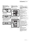
"Inverter" light
4
◗ light off: inverter OFF;
◗ light flashing green: inverter starting,
inverter ON but not connected to the
load;
◗ light shines green: normal inverter
operation;
◗ light shines red: inverter fault, the
stored alarm indicates one or several of
the following faults:
◗ ◗ inverter shutdown due to inverter
output voltage outside specified
tolerances,
◗◗ protection fuse at the inverter output
(FUS) blown,
◗◗ abnormally high inverter-output
transformer temperature,
◗◗ abnormally high inverter temperature,
◗◗ output-voltage fault (amplitude or
phase) (parallel UPSs),
◗ ◗ fault, non-calibration or non-
personalisation of the electronic control
board for the inverter,
◗◗ fault on the electronic power-supply
board.
"Load" light
5
◗ light off: load not supplied;
◗ light shines green: load supplied via
the inverter or the bypass AC source
(via the static bypass).
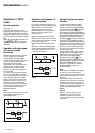
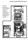
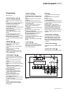
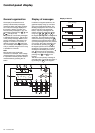
Presentation
See figure 19.
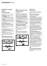
"Rectifier/charger" light
1
◗ light off: rectifier/charger OFF;
◗ light shines green: rectifier/charger
ON;
◗ light shines red: rectifier/charger fault,
the stored alarm indicates one or
several of the following faults:
◗ ◗ input switch Q1 open,
◗ ◗ protection fuse at the rectifier/charger
input (FUE) blown,
◗ ◗ abnormally high internal rectifier/
charger temperature,
◗◗ abnormally high battery charge
current,
◗ ◗ abnormally high battery voltage,
◗ ◗ fault, non-calibration or non-
personalisation of the electronic control
board for the rectifier/charger,
◗◗ fault on the electronic power-supply
board.
"Battery light"
2
◗ light off: battery float charging;
◗ light flashing green: battery
recharging;
◗ light shines green: load on battery
power;
◗ light flashing red: low-battery
shutdown warning;
◗ light shines red: battery at end of
backup time and circuit breaker QF1
open, or battery fault.
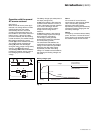
"Static-bypass" light
3
◗ light off: bypass AC source within
specified tolerances and static bypass
open;
◗ light shines green: static bypass
closed;
◗ light shines red: the stored alarm
indicates one or several of the following
faults:
◗ ◗ bypass AC source voltage or
frequency outside specified tolerances,
◗◗ static-bypass fault,
◗ ◗ abnormally high internal static-
bypass temperature,
◗◗ static-bypass ventilation fault,
◗◗ power-supply fault for the static-
bypass control function,
◗ ◗ fault on the electronic board
controlling the transfer function,
◗ ◗ non-calibration or non-
personalisation of the electronic control
board for the inverter,
◗◗ fault on the electronic power-supply
board,
◗◗ fault on monitoring the "inverter
ready" response channels (parallel
UPS system).
Buzzer
6
The buzzer sounds in the following
situations:
◗ load supplied by the bypass AC
source;
◗ load on battery;
◗ operating problems.
It sounds slowly and discontinuously for
a minor problem or when the inverter is
on battery power.
When the alarm "LOW BATTERY
SHUTDOWN" is activated, the buzzer
sounds more rapidly. Finally, if the
inverter shuts down, the beep is loud
and continuous. The buzzer may be
reset by pressing a button. If the buzzer
is reset, a higher level alarm will set it
off again.
"Full-shutdown" button
7
Pressing this button shuts down the
entire UPS (shutdown of the inverter
and rectifier/charger, opening of the
battery circuit breaker and activation of
a relay contact on the Media Contacts
11 board).
"Inverter ON" button
8
This button is used to start the inverter
locally.
"Inverter OFF" button
9
This button turns the inverter off locally.
1
2
V A W.Hz
fault
19
18
9
8
7643 521
23
2220 21
17
10 11 12 13 14 1515 16
Fig. 19
Control panel (cont.)