


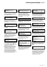
E-51028230XT/BG - 17
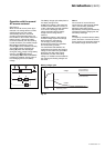
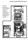
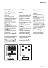
Parallel UPS unit for
increased output
See figure 21.
Proceed in the following order:
◗ check that all load devices are off or
that the load is disconnected;
◗ close the upstream switch supplying
normal AC source power (on the LV
switchboard);
◗ close the normal AC input switches
Q1 on the UPS units. The system
powers up:
◗◗ the rectifier/chargers automatically
start,
◗◗ the green "rectifier/charger" lights 1
in the control panels go on,
◗◗ lights 2 turn red;
◗ close the battery circuit breakers
QF1;
◗◗ lights 2 go off;
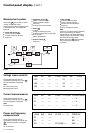
◗ close Mains 2 input switch Q4S in the
external bypass unit:
◗◗ green lights 3 and 5 on the control
panels go on;
◗ close output switches Q5N for the
inverters and in the external bypass
unit;
◗ open maintenance bypass switch
Q3BP in the external bypass unit;
◗ press the "inverter on" button 8 on
each control panel:
◗◗ the green "inverter" lights 4 flash;
◗ when a sufficient number of inverters
are ready, the inverter-output
contactors close:
◗◗ the green "inverter" lights 4 shine
permanently green;
◗◗ the "static-bypass" lights 3 go off.
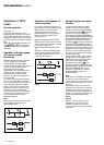
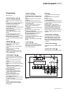
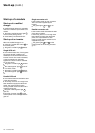
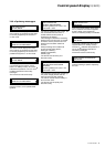
Start-up
System start-up
Single-UPS unit or
redundant parallel UPS or
UPS in "ECO" mode
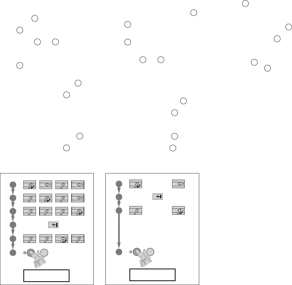
See figure 20.
Proceed in the following order:
◗ close the upstream switches
supplying normal and bypass AC
source power (on the LV switchboard);
◗ close normal AC input switch Q1.
The system powers up:
◗◗ the rectifier/charger automatically
starts,
◗◗ green light 1 on the control panel
goes on,
◗◗ light 2 turns red;
◗ close bypass AC input switch Q4S:
◗◗ green lights 3 and 5 on the control
panel go on;
◗ close inverter output switch Q5N;
◗ close battery circuit breaker QF1;
◗◗ light 2 goes off;
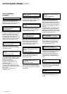
◗ open maintenance bypass switch
Q3BP;
◗ press the "inverter on" button 8 on
the control panel:
◗◗ the green "inverter" light 4 flashes,
◗◗ the inverter starts, then, if the bypass
AC source transfer conditions are
satisfied, the load is transferred to the
inverter if the on-line mode is selected,
or the load remains on the static
bypass if the "ECO" mode is selected,
◗◗ the green "static-bypass" light 3
goes off,
◗◗ the green "inverter" light 4 shines
for on-line mode or flashes for "ECO"
mode.
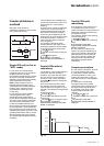
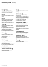
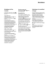
Single-converter unit or
redundant parallel
converter unit
See figure 21.
Proceed in the following order:
◗ close the upstream switch supplying
normal AC source power (on the LV
switchboard);
◗ close normal AC input switch Q1.
The system powers up:
◗◗ the rectifier/charger automatically
starts,
◗◗ green light 1 on the control panel
goes on;
◗ close battery circuit breaker QF1;
◗ close inverter output switch Q5N;
◗ press the "inverter on" button 8 on
the control panel:
◗◗ the green "inverter" light 4 flashes,
◗ ◗ the inverter starts up, then connects.
The load is then supplied by the
inverter,
◗◗ the green light 4 shines
permanently, and light
5 turns green.
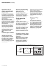
Note:
Each time a device is switched on, a
lamp test is run: all the lights turn
orange for roughly 1 second. The
message "autotest OK" is displayed
until the first primary message is sent.
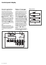
Fig. 20 Fig. 21
Q5NQ1 Q4S
QF1
0
I
3
1
2
1
0
1
0
1
0
1
0
1
0
1
0
1
0
Q3BP
1
0
1
0
1
0
1
0
1
0
1
0
1
0
1
0
1
0
5
4
6
20 - 200 kVA
3
1
2
1
0
1
0
1
0
1
0
4
20 - 200 kVA
Q5NQ1
Q5NQ1
QF1
0
I