


E-51028230XT/BG - 7
Different types of
MGE™ Galaxy™ PW
systems
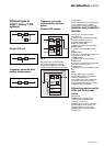
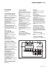
Frequency converter
without battery backup
power
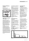
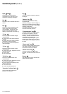
Parallel UPS system
Fig. 2
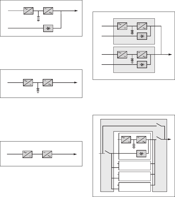
Single-UPS unit
Fig. 3
Frequency converter with
battery backup power
Fig. 4
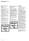
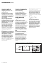
See figure 5 showing two parallel-
connected (redundant) UPS units.
A static bypass (C) does not exist in
parallel-connected frequency-converter
configurations.
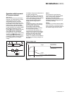
When increased power is required (two
to four parallel units), an external
bypass must be added (see figure 6).
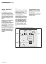
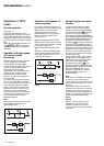
Isolation and protection
devices
(See figure 1 on previous page):
◗ Q1 (switch):
◗◗ isolation of the rectifier/charger (A)
from the normal AC source (1);
◗◗ rectifier/charger (A) start-up;
◗ QF1 (circuit breaker):
◗◗ battery (D) protection and isolation;
◗ Q5N (switch):
◗◗ isolation of the UPS (B) from the
load;
◗ Q4S (switch):
◗ ◗ isolation of the static bypass (C) from
the bypass AC source (2);
◗ Q3BP (switch):
◗◗ bypass switch for maintenance;
◗ FUE (fuses):
◗◗ protection of the rectifier/charger (A)
from the normal AC source;
◗ FUS (fuses):
◗◗ protection of the inverter (B) from the
load.
Note:
◗ switch Q3BP does not exist on
parallel UPS systems constituted to
increase available power;
◗ the "Q3BP" and "Q4S" switches do
not exist on frequency converters;
◗ circuit breaker QF1 does not exist on
installations without batteries.
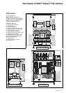
External bypass for parallel
UPSs and the hot-swap
option
See figure 6.
◗ Q5N (switch): isolation of the
inverters of all the parallel UPS
systems from the load;
◗ Q4S (switch): isolation of the static
bypasses (C) on each parallel unit
from the bypass AC source (2);
◗ Q3BP (switch): bypass switch for
maintenance.
1
2
AB
C
D
1
AB
D
1
AB
Fig. 6
2
1
Q3BP
Q4S
Galaxy 1
Galaxy 2
2
1
Galaxy 3
2
1
Galaxy 4
2
2
Q5N
1
Fig. 5
1
D
2
B
A
1
D
2
B
A
C
C
Introduction (cont.)