


14 - E-51028230XT/BG
Control panel
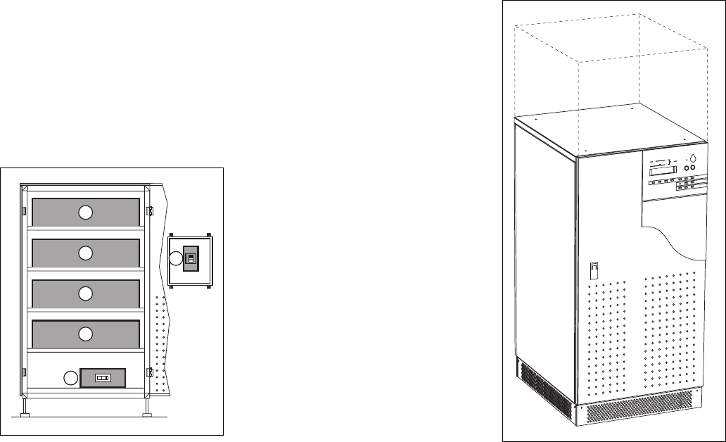
Battery cubicle
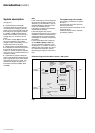
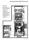
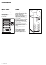
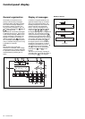
Figure 17 shows an example of
component layout in a battery cubicle
or a battery circuit-breaker enclosure.
Legend for figure 17:
1 - battery isolation and protection
circuit breaker QF1,
2 - battery cells.
Fig. 17
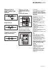
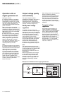
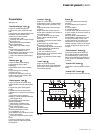
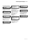
General
The control panel on
MGE™ Galaxy™ PW UPSs comprises
the basic controls and indications
required to check the general status of
the system (see figure 19).
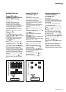
Located in the upper right part of the
cubicle front, the control panel is
designed to provide an easy and rapid
overview of system status (see figure
19 on next page).
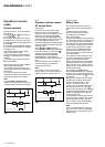
Interpretation of symbols is very simple
and requires no particular training.
The information concerns only the
cubicle on which the panel is located.
The panel indicates:
◗ normal operation (load protected);
◗ operation with load on battery power;
◗ abnormal situations (operating
problem);
◗ dangerous situations (load not
protected).
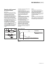
Note:
The information on the bypass AC
source provided below does not
concern frequency converters.
Information on batteries does not
concern frequency converters without
batteries.
Fig. 18
2
2
2
2
1
1