


E-51028230XT/BG - 9
Operation with the normal
AC source restored
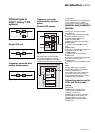
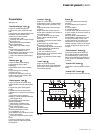
See figure 9.
When normal AC source power (1) is
restored or its voltage returns to within
specified tolerances, the system
automatically returns to its normal
operating mode described above (on
the condition it did not reach the end of
battery power). If the end of battery
power was reached (with the resulting
inverter shutdown), the rectifier/charger
(A) restarts automatically, but the
inverter (B) must be restarted manually.
The rectifier/charger recharges the
battery (D) which was discharged
during the mains outage. During battery
charging, light
2 flashes green.
The message "BATTERY CHARGING"
is displayed, together with the value of
the recharging current and battery
voltage.
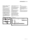
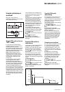
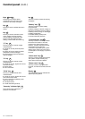
The battery charge cycle takes place in
two steps (see figure 10):
◗ step 1: the battery is recharged at a
constant current limited to 0.1C10 (i.e.
1/10th of the battery capacity specified
for a 10 hour discharge). The DC
voltage increases with the battery
charge until the charge level is
reached;
◗ step 2: the battery is recharged at
constant voltage equal to the charge
level (maximum value 463 V).
The charging current gradually
decreases until reaching a specified
low value (floating current).
For vented lead-acid batteries, the
rectifier/charger supplies the charging
voltage for 0 to 255 hours (parameter
defined by the after-sales support
department) and then the floating
voltage. For sealed lead-acid batteries,
the charging and floating voltages are
the same.
Note 1:
If the normal AC source failure is
shorter than 0 to 255 seconds (default
value = 30 seconds) (parameter
defined by after-sales support
department), the charger automatically
supplies the floating voltage given the
low battery discharge.
Note 2:
In frequency converters without battery
power, the return of normal AC source
power results in the automatic restart of
the rectifier/charger and the inverter.
Fig. 9
1
2
AB
C
D
2
1
4 521
U/I
current
limiting
0,1 C10
constant voltage
decreasing current
voltage
current
t
U charge/floating
(sealed batteries)
U "floating"
(vented batteries)
Fig. 10
Battery charge cycle
Introduction (cont.)