


E-51028230XT/BG - 29
◗ signal to open battery circuit
breaker(s) QF1 in the event the
"emergency off" button is pressed or to
avoid an excessive battery discharge
(lasting more than three times the rated
backup time plus two hours);
◗ full-shutdown contact (volt-free
changeover contact) used to trip
switching devices in the event of an
emergency shutdown or a full shutdown
(button
7 ).
◗ "general alarm" information (volt-
free changeover contact) which
includes:
◗ ◗ internal faults,
◗ ◗ information on temperatures outside
tolerances in the battery room
(optional),
◗ ◗ overload information (> In),
◗◗ static-switch ventilation and power-
supply faults.
Note:
◗ The maximum breaking capacity of
the changeover contacts is 5A at 250V;
◗ information on the battery is not
supplied to frequency converters
without a battery.
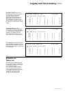
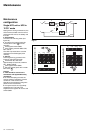
Environment information
Terminals XR2, XR3, XR4 and XR5 on
the "Media Contacts 11" board of each
type of unit can be used to receive
signals from the operating environment
and to transmit signals concerning the
operating status of the UPS (see figure
16 for the position of the board, item
12).
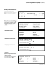
Signal reception
The signals should be provided by volt-
free contacts.
◗ emergency off:
An NC contact causes shutdown of the
inverter and the rectifier/charger,
opening of the battery circuit breaker
and activation of a relay contact on the
"Media Contacts 11" board;
◗ battery room ventilation fault:
An NO contact causes shutdown of the
rectifier/charger;
◗ battery circuit breaker QF1 closed:
An NO contact prevents inverter start-
up if the circuit breaker is open;
◗ battery temperature:
A PC-board, placed near the battery,
supplies information on the battery
temperature, thus enabling the rectifier/
charger to regulate the battery voltage;
◗ "auxiliary" signals:
Depending on the selected settings,
these signals may be used to provoke:
◗◗ forced shutdown of the inverter
(whatever the status of the bypass AC
source),
◗◗ protected shutdown of the inverter
(load transfer to the bypass AC
source),
◗◗ a change in the inverter output
frequency (50 Hz or 60 Hz).
◗ ◗ limiting of the current drawn by the
rectifier/charger (programmable value)
when supplied by an engine generator
set with an insufficient power rating.
The additional power required by the
inverter is supplied by the battery which
discharges,
◗ ◗ limiting of the battery charge current
(programmable value) if the normal AC
source is replaced by an engine
generator set with an insufficient power
rating.
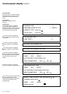
Signal transmission
◗ an auxiliary 24 V power supply,
isolated and backed up, is used to
supply:
◗◗ the undervoltage release of the
battery circuit breaker(s) QF1,
◗◗ the board that measures the
temperature in the battery room;
◗ "low battery" warning signal (volt-
free changeover contact) indicating that
battery time is about to run out. The
warning threshold may be
personalised;
◗ "load on UPS" signal (volt-free
changeover contact) indicating that the
load is supplied by the inverter. For a
single-UPS unit, one volt-free
changeover contact may be used to
indicate that the load is supplied by the
bypass AC source;
◗ "load on battery power" signal
(volt-free changeover contact)
indicating that the inverter is supplied
by the battery in the following cases:
◗◗ normal AC source outage or voltage
drop,
◗ ◗ rectifier/charger shutdown,
◗◗ rectifier/charger current limiting.
This signal, which may be used to
initiate process saving and shutdown
procedures, is time-delayed 30
seconds to avoid unnecessary
operations following micro-breaks;
◗ "maintenance position" signal
(volt-free changeover contact)
indicating that:
◗◗ maintenance bypass switch Q3BP is
closed,
◗ ◗ bypass AC source input switch Q4S
is open,
◗ ◗ inverter output switch Q5N is open,
◗◗ battery circuit breaker QF1 is open;