


E-51028230XT/BG - 35
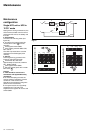
Redundant, parallel UPS
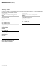
See figures 27 and 28 in the Appendix.
During maintenance, a UPS unit must
be isolated from the normal AC source,
its battery and the output circuits of the
other UPS units.
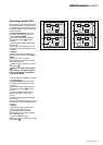
◗ isolate one UPS (see figure 27)
Proceed in the following order (see
figure 25 without Q3BP):
◗◗ shut down the inverter (press the
"inverter OFF" button 9 for three
seconds),
◗◗ open isolating switches Q5N, Q4S,
QF1 and Q1.
The UPS unit is powered down once
the capacitors have discharged (a few
minutes);
◗ start-up
Following servicing, proceed in the
following order (see figure 26 without
Q3BP):
◗◗ close switch Q1, then after
approximately ten seconds, switches
QF1, Q5N and Q4S,
◗◗ start the inverter (press the "inverter
ON" button 8 ).
Note: if the load is still supplied
by an inverter, the Q3BP switch on
the unit undergoing maintenance
must not be closed.
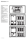
To fully isolate the installation, proceed
as indicated below:
◗ isolate all UPSs (see figure 28)
Proceed in the following order (see
figure 25):
◗◗ shut down the inverters (press the
"inverter OFF" buttons
9 for three
seconds),
◗ ◗ close the Q3BP switches used to
bypass the units (no units have
priority),
◗◗ open isolating switches Q5N, Q4S,
QF1 and Q1.
The UPS units are powered down once
the capacitors have discharged (a few
minutes).
◗ start-up
Following servicing, proceed in the
following order (see figure 26):
◗◗ close switches Q1, then after
approximately ten seconds, switches
QF1, Q5N and Q4S,
◗◗ open the Q3BP switches,
◗◗ start the inverters (press the "inverter
ON" buttons
8 ).
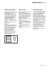
Fig. 27 Fig. 28
1
D
2
B
A
Q3BP
Q1
Q5N
Q4S
QF1
C
1
D
2
B
A
Q3BP
Q1
Q5N
Q4S
QF1
C
1
D
2
B
A
Q3BP
Q1
Q5N
Q4
QF1
C
1
D
2
B
A
Q3BP
Q1
Q5N
Q4S
QF1
C
Maintenance (cont.)