42
Appendix: Multiple SmartSlot Installation
If your UPS configuration uses more than one SmartSlot device, you
must install them in the correct order for them to work together properly.
A SmartSlot device with higher priority is to be placed in the SmartSlot
labeled with the higher number. Refer to the table that follows.
2
3
1
Status
Power
Monitoring Port
To UPS
24 VDC
–
+
–
Management Port
Status
AP9608 Call-UPS Remote Mgt Device
Smart SlotSmart Slot
Smart SlotSmart Slot
Reset
Status
Link - RX/TX
AP9605 PowerNet™ SNMP Adapter™
Smart SlotSmart Slot
Probes
1 2
Sensor Zones
AP9612 Measure-UPS™
1 2 3 4
GND
DEVICE PART # PRIORITY POSITION
PowerNet SNMP
Adapter
AP9605 Highest Highest-numbered slot.
Call-UPS
II
Remote UPS
Management Device
AP9608
Second
Highest
Second-highest-numbered
slot (highest if no PowerNet
SNMP Adapter is present).
Relay I/O Module AP9610 Medium
Any slot numbered lower
than PowerNet SNMP
Adapter & Call-UPS
II
and
higher than Measure-UPS.
Interface Expander AP9607 Medium
Any slot numbered lower
than PowerNet SNMP
Adapter & Call-UPS
II
and
higher than Measure-UPS.
Measure-UPS AP9612TH Lowest Lowest numbered slot.
Triple Chassis
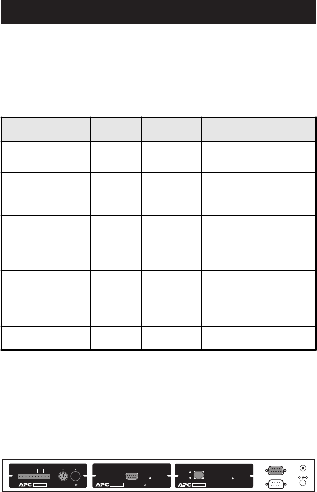
To install SmartSlot devices in the APC Triple Chassis (AP9604), note
that the slots are numbered on the rear panel. The following figure shows
the rear panel of the Triple Chassis with the PowerNet
SNMP Adapter
installed in slot #3, Call-
UPS II in slot #2 and Measure-UPS II in slot #1.


