17
Connecting to Protected Devices
Connection
procedure
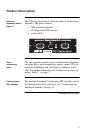
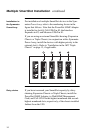
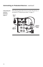
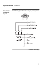
To connect the devices, refer to “Connecting the Interface
Expander: Figure 2” on page 18 and perform the following
steps in the order given.
1 Connect the master server to the (Advanced) com-
puter interface port of the UPS. (See “Master
server versus Interface Expander servers” on page
8.)
Note: A server not supported by PowerChute plus
must use simple signaling with the appropri-
ate cable. (See “Choosing cables: Table 1”
on page 4.)
If an accessory, such as Call-
UPS II
or
Measure-
UPS II
, is already using the
(Advanced) computer interface port of the
UPS
, connect the master server to the
UPS
monitoring port on the accessory. (Accesso-
ries label this port in different ways, but the
function—replicating the computer inter-
face port of the
UPS
—is the same.)
2 Connect the other server(s) to the Basic ports on
the Interface Expander, using
APC
cables. See
“Choosing cables: Table 1” on page 4.
Note: Servers connected to the Basic ports of the
Interface Expander use simple signaling
for monitoring the UPS. If these servers use
PowerChute plus, this software must be
configured for simple signaling. See “Con-
figuring PowerChute plus for simple
signaling” on page 9.
3 Connect the power cords of all protected servers
and devices to the power outlets on the
UPS
.
4 Continue with “Configuring the Interface
Expander” on page 19.
Continued on next page