5
Product Description
Interface
Expander panel:
Figure 1
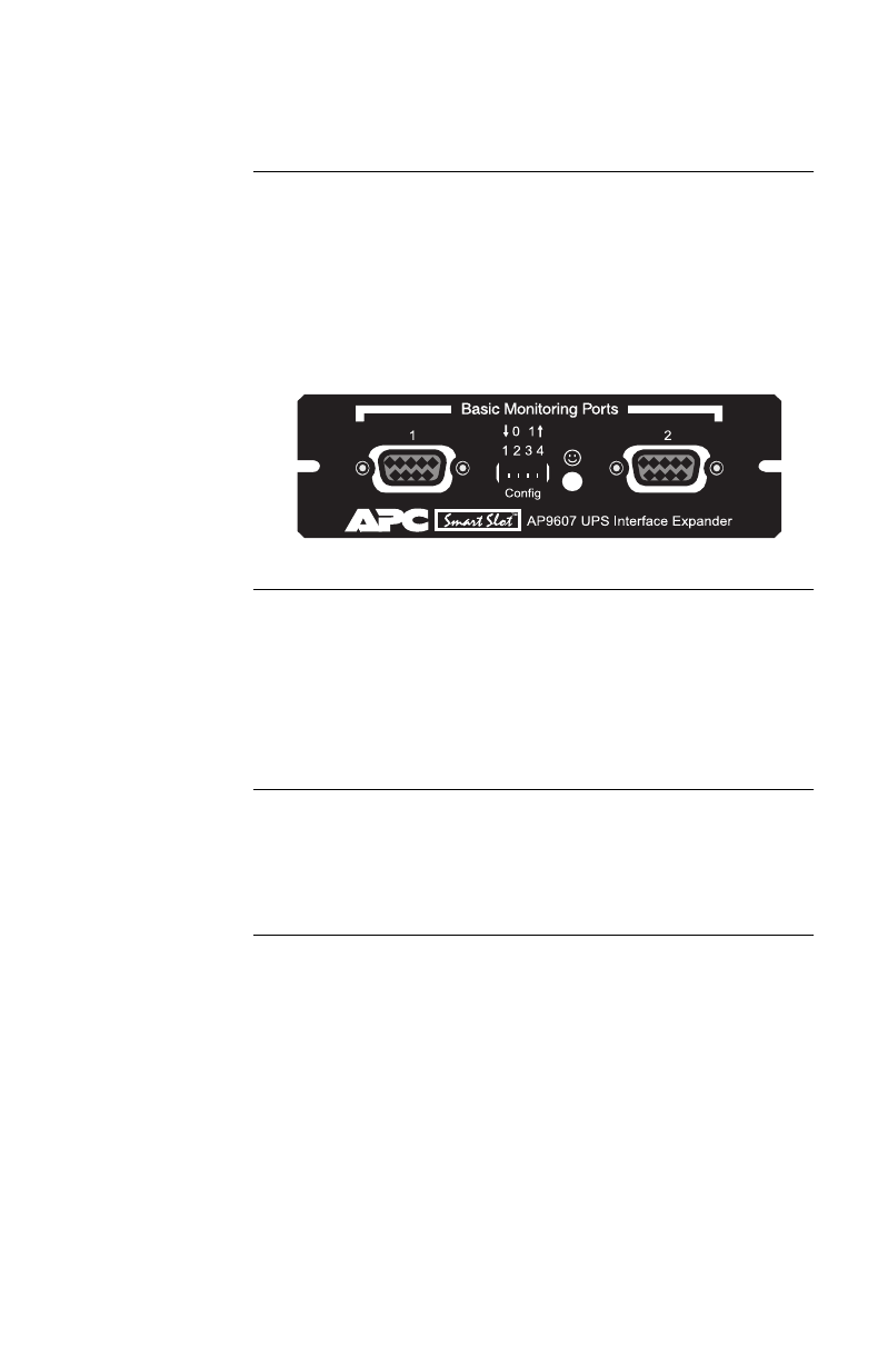
The following figure shows the front panel of the Interface
Expander. The panel contains:
• 2 Basic monitoring ports
• 4 Configuration DIP switches
• a status LED
Figure 1:Interface Expander panel
Basic
monitoring
ports
The two computer interface ports on the Interface Expander
are called
Basic
ports because they supply simple UPS sig-
naling for On Battery and Low Battery conditions in the
UPS. For further information see “Simple versus smart sig-
naling: Table 3,” on page 7.
Configuration
DIP switches
The Interface Expander Configuration DIP switches control
the shutdown operation of the unit. See “Configuring the
Interface Expander” on page 19.
Continued on next page


