


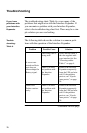


30
Specifications
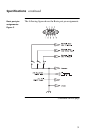
Basic port pin
assignments
The following limitations and capabilities apply to the Basic
ports of the Interface Expander:
• Pins 3, 5, and 6 are open collector outputs which must
be pulled up to a common referenced supply no
greater than +
40 VDC
. The transistors are capable of
a maximum non-inductive load of 25 mA. Use only
Pin 4 as the common.
• The output at Pin 2 generates a low-to-
hi
g
h RS-232
level when the device is signaling an On Battery con-
dition. The pin is normally at a low
RS-232
level.
• The Interface Expander unit may be signaled to shut
down the
UPS
by applying a high
RS-232
level to Pin
1 for 4.5 seconds. Shutdown is also dependent on the
UPS
status and the Interface Expander shutdown
mode (see “Configuring the Interface Expander,” on
page 19).
Continued on next page