


®
USER’S GUIDE
network management card
50
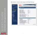
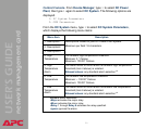
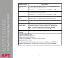
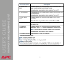
8- Current Limit
Alarm
The alarm action that occurs if one or more rectifiers have been
forced into the “current limited” mode.
Allowed values: any standard alarm selection
a
or n of N
b
.
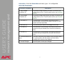
9- Standby Alarm The alarm action that occurs if the control unit is holding one or
more rectifiers in the standby mode.
Allowed values: any standard alarm selection
a
or n of N
b
.
10- Fan Failure
Alarm
The alarm action that occurs if the fan fails in one or more rectifiers.
Allowed values: any standard alarm selection
a
or n of N
b
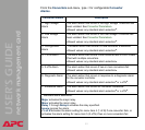
11- Failure Alarm The alarm action that occurs if the output of one or more rectifiers
fails.
12- Hardware
Voltage Alarm
The alarm action that occurs if rectifier voltage is outside
reasonable limits or if a voltage measurement failure occurs.
Note: There is a single rectifier voltage for all rectifiers.
Allowed values: any standard alarm selection
a
.
13- Accept
Changes
Use this option to save your changes.
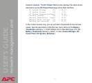
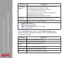
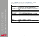
Rectifier Alarms Description
a
Standard alarm selections:
• Major activates the major relay.
• Minor activates the minor relay.
• Relay 1 through Relay 6 activates the relay specified.
• Ignore ignores the alarm.
b
n of N activates the alarm setting for menu item 4 (1 of N) if one rectifier fails, or
activates the alarm setting for menu item 5 (2 of N) if two or more rectifiers fail.