


Manual-4
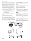
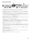
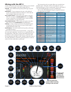
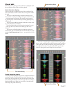
Rear Panel Description
1 Universal Voltage Input: via a miniature IEC 60320 C6 appliance inlet. is mates with an IEC 60320 C5 line cord (USA
domestic). Do not lift the ground connection!
2
USB
connection: Attach the included USB cable from here to the computer. e blue LED illuminates when the cable is con-
nected and receiving power. USB delivers two stereo inputs from the computer to the mixer (
USB 1
and
USB 2
), and one stereo
record signal from the mixer to the computer.
3
HOUSE
Output: e front panel
HOUSE LEVEL
control aects the volume at this Output. Connect either the XLR or ¼" TRS
(tip-ring-sleeve) jacks to a balanced equalizer or amplier. Both Output types may be used simultaneously if needed. ough not
recommended, unbalanced ¼" TS (tip-sleeve) cables may be used for short runs (under 3 meters [10 feet]) to an amplier with
unbalanced inputs. See the RaneNote “Sound System Interconnection” for wiring recommendations.
4
AUX
Output: is delivers the same signal as the
HOUSE
Output, but has its own rear panel LEVEL control. is Output is not af-
fected by the front panel
HOUSE LEVEL
control. ese balanced ¼" TRS (tip-ring-sleeve) Outputs connect to a balanced equalizer
or amplier (for a possible second listening zone) and follow the same interconnection rules as above.
5 MIC TO USB RECORD switch: In the YES position the Mic signal along with the Program mix is routed to the USB record output.
In the NO position only the Program mix is sent to the USB record output.
6
INPUTS 1 & 2
: ese stereo Inputs are each switchable from a PHONO (RIAA) stage for magnetic cartridges (switch in) to a LINE
level Input suitable for any line level device such as a CD player (switch out). Each of these may be assigned to
PROGRAM A
or
B
using the front panel
INPUT
selectors. e PHONO GROUND screw connects those extra wires coming out of the turntables.
7
MIC
Input jack: Accepts either a ¼" balanced (TRS) or unbalanced (TS) microphone plug, controlled by the front panel
MIC
LEVEL
control.
MADE IN U.S.A.
RANE CORP.
RIGHT LEFT RIGHT RIGHTLEFT LEFT
LEVEL
R
L
PHONO
LINE
PHONO
GROUND
MIC TO
USB RECORD
MP 4
HOUSE AUX
IN 2 IN 1
MIC
ACN 001 345 482
BALANCED OUTPUTS: TIP = (+), RING = (–), SLEEVE = SIGNAL GROUND BALANCED INPUT
PHONO
LINE
YES
NO
USB
100-240V
50/60 Hz 7 WATTS
FOR CONTINUED
GROUNDING PROTECTION
DO NOT REMOVE SCREW
COMMERCIAL AUDIO
EQUIPMENT 24TJ
R
1 2 7 5 6
3 4
Fader Cleaning
With heavy use in harsh environments, the fader may need lu-
brication. is treatment extends longevity and can make a used
fader as good as new. e fader assembly must be removed from
the MP 4 for proper cleaning. We recommend any of the follow-
ing cleaning solutions:
Caig DeoxIT FaderLube
F100 spray lubricant (www .c aig.com)
Caig DeoxIT FaderLube F5 spray cleaner (www.caig.com)
CRC 2-26 (www. crcindustries.com)
Order CaiLube MCL
®
from:
CAIG Laboratories, Inc.
12200 atcher Ct.
Poway, CA 92064
Phone 858-486-8388
Fax 858-486-8398
Web www.caig.com
CLEANING INSTRUCTIONS
A. Fader assembly replacement (part #11646)
1. Unplug the MP 4.
2. Remove the bottom cover.
3. Remove the fader screws from the front panel.
4. Draw fader assembly out through the bottom.
5. Remove ribbon cable from old fader.
6. Attach ribbon cable to new fader, screw onto front panel and
replace bottom cover.
B. Fader cleaning
1. Hold the fader assembly away from the mixer.
2. Position the fader at mid-travel.
3. Spray cleaner/lubricant into both ends of the fader in sucient
amounts to flush debris.
4. Move the fader over its full travel back and forth a few times.
5. Shake excess uid from the fader assembly.
6. Wipe o excess uid.