


19
IntraCore IC3624PWR Layer 2 PoE Switch with Dual Gigabit
Chapter 4: Connecting Network Devices
The switch is designed to interconnect multiple segments (or collision domains). It can be connected to network cards
in PCs and servers, and to hubs, routers, or other switches.
4.1 Twisted-Pair Devices
Each device requires an unshielded twisted-pair (UTP) cable with RJ-45 connectors at both ends. Use Category 5 for
100BaseTX connections, and Category 3, 4 or 5 for 10BaseT connections.
4.1.1 Cable Guidelines
The RJ-45 ports on these switches support automatic MDI/MDI-X pinout configuration, so you can use standard
straight-through twisted-pair cables to connect to any other network device (PCs, servers, switches, routers, or hubs).
Caution:
Do not plug a phone jack connector into an RJ-45 port. Doing this will damage the switch. Use only
twisted-pair cables with RJ-45 connectors that conform to FCC standards.
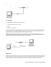
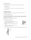
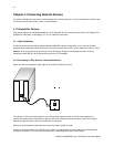
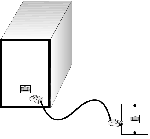
4.1.2 Connecting to PCs, Servers, Hubs and Switches
Attach one end of a twisted-pair cable segment to the device’s RJ-45 connector.
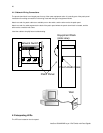
If the device is a PC card and the switch is in the wiring closet, attach the other end of the cable segment to a
modular wall outlet that is connected to the wiring closet. (See “Network Wiring Connections” later in this chapter.)
Otherwise, attach the other end to an available port on the switch.
Make sure each twisted pair cable does not exceed 100 meters (328 ft) in length.
As each connection is made, the Link LED (on the switch) corresponding to each port lights up to indicate that the
connection is complete. (For more LED information see, “Interpreting LEDs” later in this chapter.)