


Chapter 4: Motherboard informationChapter 4: Motherboard information
Chapter 4: Motherboard informationChapter 4: Motherboard information
Chapter 4: Motherboard information
4-164-16
4-164-16
4-16
13.13.
13.13.
13.
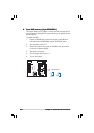
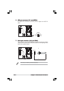
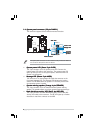
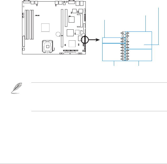
Auxiliary panel connector (20-pin AUX_PANEL1)Auxiliary panel connector (20-pin AUX_PANEL1)
Auxiliary panel connector (20-pin AUX_PANEL1)Auxiliary panel connector (20-pin AUX_PANEL1)
Auxiliary panel connector (20-pin AUX_PANEL1)
This connector is for additional front panel features including front panel
SMB, locator LED and switch, chassis intrusion, and LAN LEDs.
•
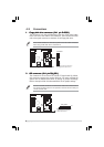
Front panel SMB (6-1 pin FPSMB)Front panel SMB (6-1 pin FPSMB)
Front panel SMB (6-1 pin FPSMB)Front panel SMB (6-1 pin FPSMB)
Front panel SMB (6-1 pin FPSMB)
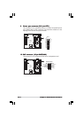
These leads connect the front panel SMBus cable.
•
LAN activity LED (2-pin LAN1_LED, LAN2_LED)LAN activity LED (2-pin LAN1_LED, LAN2_LED)
LAN activity LED (2-pin LAN1_LED, LAN2_LED)LAN activity LED (2-pin LAN1_LED, LAN2_LED)
LAN activity LED (2-pin LAN1_LED, LAN2_LED)
These leads are for Gigabit LAN activity LEDs on the front panel.
•
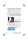
Chassis intrusion (2-pin CHASSIS)Chassis intrusion (2-pin CHASSIS)
Chassis intrusion (2-pin CHASSIS)Chassis intrusion (2-pin CHASSIS)
Chassis intrusion (2-pin CHASSIS)
These leads are for the intrusion detection feature for chassis
with intrusion sensor or microswitch. When you remove any
chassis component, the sensor triggers and sends a high-level
signal to these leads to record a chassis intrusion event.
•
Locator LED (6-pin LOCATOR)Locator LED (6-pin LOCATOR)
Locator LED (6-pin LOCATOR)Locator LED (6-pin LOCATOR)
Locator LED (6-pin LOCATOR)
These leads are for the locator switch and LED on the front panel.
P5MT-R
®
P5MT-R Auxiliary panel connector
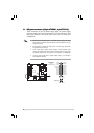
AUX_PANEL1
I2C_4_DATA#LOCATORLED1+
+5VSBLOCATORLED1-
LAN1_LINKACTLED-LOCATORBTN#
LAN1_LINKACTLED+GND
+5VSB
I2C_4_CLK#
GNDGND
LAN2_LINKACTLED+LOCATORLED2-
LAN2_LINKACTLED-LOCATORLED2+
CASEOPEN
1
NC
Front panel SMBFront panel SMB
Front panel SMBFront panel SMB
Front panel SMB
LAN activity LEDLAN activity LED
LAN activity LEDLAN activity LED
LAN activity LED
Chassis intrusionChassis intrusion
Chassis intrusionChassis intrusion
Chassis intrusion
Locator LEDLocator LED
Locator LEDLocator LED
Locator LED
and switchand switch
and switchand switch
and switch
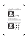
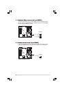
By default, a cable plug (6x2, 12-pin) connects the AUX_PANEL1 to the
front panel I/O board. The Pin1 on the cable plug is located at the top right
corner on the “
I2C_4_DATA#I2C_4_DATA#
I2C_4_DATA#I2C_4_DATA#
I2C_4_DATA#” lead and is marked by a triangle. Take
note of the Pin1 when reconnecting the cable plug to prevent incorrect
insertion.
Connector Pin 1Connector Pin 1
Connector Pin 1Connector Pin 1
Connector Pin 1