


Location and Functions of Control
5975696 BARCODATA 2100 140798
5-3
Location and Functions of Control
5975696 BARCODATA 2100 140798
5-3
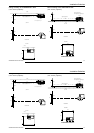
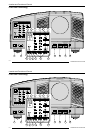
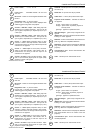
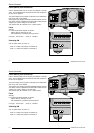
Power switch : '1' = on, '0' = off
Power input : switchable between 120 VAC and
230 VAC
IR receiver : receiver for control signals transmitted from
the RCU.
Diagnostics code : a) source number
b) error code : a two digit error code is displayed when
something goes wrong inside the projector.
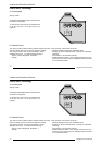
Source 5 : RGB H/C V input : RGB analog input with
standard sync on 5 BNC connectors. The sync can be
sync on green, composite sync, separate sync (H & V) or
3 level sync.
Source 4 : RGB H/C V input : RGB analog input with
standard sync on 5 BNC connectors. The sync can be
sync on green, composite sync or separate sync (H & V)
Source 1 : Video input (composite video) on BNC
connector. Allows a video tape recorder, video camera,
color receiver/monitor, etc. having a video line output to be
connected to the projector.
Source 2 : Video input on Cinch (RCA) connector.
Allows a video tape recorder, video camera, color re-
ceiver/monitor, etc. having a video line output to be
connected to the projector.
Source 3 : S-Video on 4-pin mini-DIN connector. Sepa-
rate Y/C (luma-chroma) signal inputs for higher quality
playback of Super VHS signals.
AUDIO IN : 3 audio inputs on 2 Cinch (RCA) connectors
for audio (L-R).
MUTE LED : lit up when mute key is pressed.
AUDIO OUT : 2 x Cinch (RCA) stereo audio output.
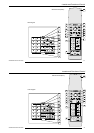
Projector mode indication : indicates the status of
the projector.
no light : power switch is not pressed.
red light : power switch is pressed, projector in
stand by mode.
green light : projector in operational mode.
IR-Acknowledged : (green LED) IR signals are rec-
ognized.
IR-Received : (red LED) IR signals are received without
knowing for which projector.
RS232 IN : to allow communication with external com-
puter, e.g. IBM PC or compatible, Macintosh ...
RS232 OUT : used to connect to next projector, RS232IN
plug (communication link for PC or MAC to the next
projector).
Communication port : allows communication with
the 800 peripherals.
CTRL : remote input for wired remote control.
1
2
3
4
5
6
7
8
9
10
12
11
13
14
15
16
17
18
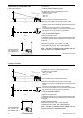
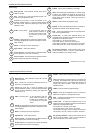
Power switch : '1' = on, '0' = off
Power input : switchable between 120 VAC and
230 VAC
IR receiver : receiver for control signals transmitted from
the RCU.
Diagnostics code : a) source number
b) error code : a two digit error code is displayed when
something goes wrong inside the projector.
Source 5 : RGB H/C V input : RGB analog input with
standard sync on 5 BNC connectors. The sync can be
sync on green, composite sync, separate sync (H & V) or
3 level sync.
Source 4 : RGB H/C V input : RGB analog input with
standard sync on 5 BNC connectors. The sync can be
sync on green, composite sync or separate sync (H & V)
Source 1 : Video input (composite video) on BNC
connector. Allows a video tape recorder, video camera,
color receiver/monitor, etc. having a video line output to be
connected to the projector.
Source 2 : Video input on Cinch (RCA) connector.
Allows a video tape recorder, video camera, color re-
ceiver/monitor, etc. having a video line output to be
connected to the projector.
Source 3 : S-Video on 4-pin mini-DIN connector. Sepa-
rate Y/C (luma-chroma) signal inputs for higher quality
playback of Super VHS signals.
AUDIO IN : 3 audio inputs on 2 Cinch (RCA) connectors
for audio (L-R).
MUTE LED : lit up when mute key is pressed.
AUDIO OUT : 2 x Cinch (RCA) stereo audio output.
Projector mode indication : indicates the status of
the projector.
no light : power switch is not pressed.
red light : power switch is pressed, projector in
stand by mode.
green light : projector in operational mode.
IR-Acknowledged : (green LED) IR signals are rec-
ognized.
IR-Received : (red LED) IR signals are received without
knowing for which projector.
RS232 IN : to allow communication with external com-
puter, e.g. IBM PC or compatible, Macintosh ...
RS232 OUT : used to connect to next projector, RS232IN
plug (communication link for PC or MAC to the next
projector).
Communication port : allows communication with
the 800 peripherals.
CTRL : remote input for wired remote control.
1
2
3
4
5
6
7
8
9
10
12
11
13
14
15
16
17
18