


24
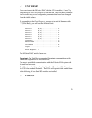
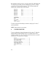
The V93A has five LEDs on the rear panel that indicate the modem status:
TD, RD, CD, MR, and CX. These LEDs are described below.
LED Description
TD Transmit Data: Indicates the modem is transmitting data.
RD Receive Data: Indicates the modem is receiving data.
CD Carrier Detect: Indicates a valid carrier tone has been detected.
MR Modem Ready: Indicates the modem is ready to communicate.
CX Connection: Indicates the V93A has a connection to the main board, to a module, or to
an individual channel or port.
7 V93A EPROM UPGRADE
You will receive one EPROM (chip with label) for each module to be
upgraded.
The materials you will need to supply are:
Flat blade screwdriver
IC DIP extractor or a pair of curved needle-nose pliers
1. IMPORTANT: Remove power from the unit by depressing the
power switch on the front of the unit to OFF. Also remove power
cord from the AC outlet.
2. Remove the appropriate module by loosening the 2 straight slot
screws that attach the connector board I/O module to the chassis and
then pulling the module out.
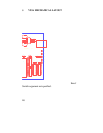
3. Refer to Appendix B (V93A Mechanical Layout) and locate socket
U2. Remove existing EPROM from socket U2 with IC extractor or
needle-nose pliers. Gradually loosen each side of the chip, alternating